Ransburg, Mma-570 direct/indirect charge - maintenance – Ransburg MMA-570 Direct_Ind Charge Atomizer A13366 User Manual
Page 66
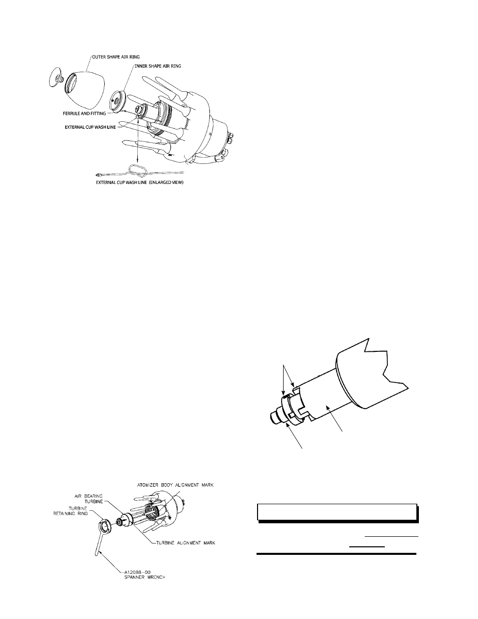
Interior/Exterior Shaping Air Manifold Removal
Reassembly
(Lightly lubricate all O-rings prior to assembling.)
Carefully install the inner shaping air ring onto the
turbine threads. Tighten in a clockwise direction
until it seats against the turbine. Tighten set
screw to 5 lbs•in (0.564 Nm) torque to prevent
shaping air ring/manifold from rotating. Do not
over-tighten! If replacing the solvent tube, install
into the atomizer body first and tighten with a 3/16”
end-wrench. Before installing the other end into
the inner shaping air ring, check the position of
the 1/4-20 threaded hole. If it is less than 180°
from the fitting installed in the atomizer body, you
must install a loop (as shown in “Installing Loop
In Tubing” figure) to prevent tube from becoming
pinched when outer shaping air ring is installed.
Do not kink the tube when installing loop (see
“Interior/Exterior Shaping Air Manifold Removal”
figure).
Turbine Removal/Replacement
Removal
Remove the turbine retaining ring by using the
spanner wrench (A12088-00), turning the turbine
retaining ring in a counter-clockwise direction. Pull
the turbine out while rocking it from side to side.
Turbine Removal
Replacement
Apply a light coating of O-ring lubricant to all the
O-rings and the threads of the turbine and turbine
retaining ring prior to assembly. Push the turbine
down into the cavity in the atomizer body. Align the
mark on the turbine with the mark on the atomizer
body. Install the turbine retaining ring and o-ring
by hand. Use the spanner wrench to tighten an
additional 1/8-1/4 turn. (Lightly lubricate O-ring
with petroleum jelly.) Check centering of fluid tube.
If fluid tube is centered, the turbine is fully seated.
If not, check tightness with spanner wrench. If
tube is not centered, again remove turbine and
check for causes, such as an O-ring fell off, fiber
optic not fully installed, foreign material on seating
surface, etc. Reinstall and recheck tube centering.
Fluid Tip Removal / Replacement
Removal
To remove the fluid tips, use the tip/tube removal
tool (A11229-00). Insert the tool over the tip and
engage the four (4) prongs of the tool into the four
(4) slots in the tips (see “Fluid Tip Removal” figure).
Fluid Tip Removal
To remove, turn the tip CLOCKWISE.
The thread on the tip is left hand.
NOTE
ENGAGE PRONGS
INTO SLOTS
A11229-00 TOOL
FLUID TIP
MMA-570 Direct/Indirect Charge - Maintenance
Ransburg
LN-9279-13
63