11 ethernet-i/p interface – FEC AFC1500 User Manual
Page 99
AFC1500 Multi-2 Unit Hardware Manual (Rev2.1)
PAGE 5 - 55
Chapter 5: Control Interfaces
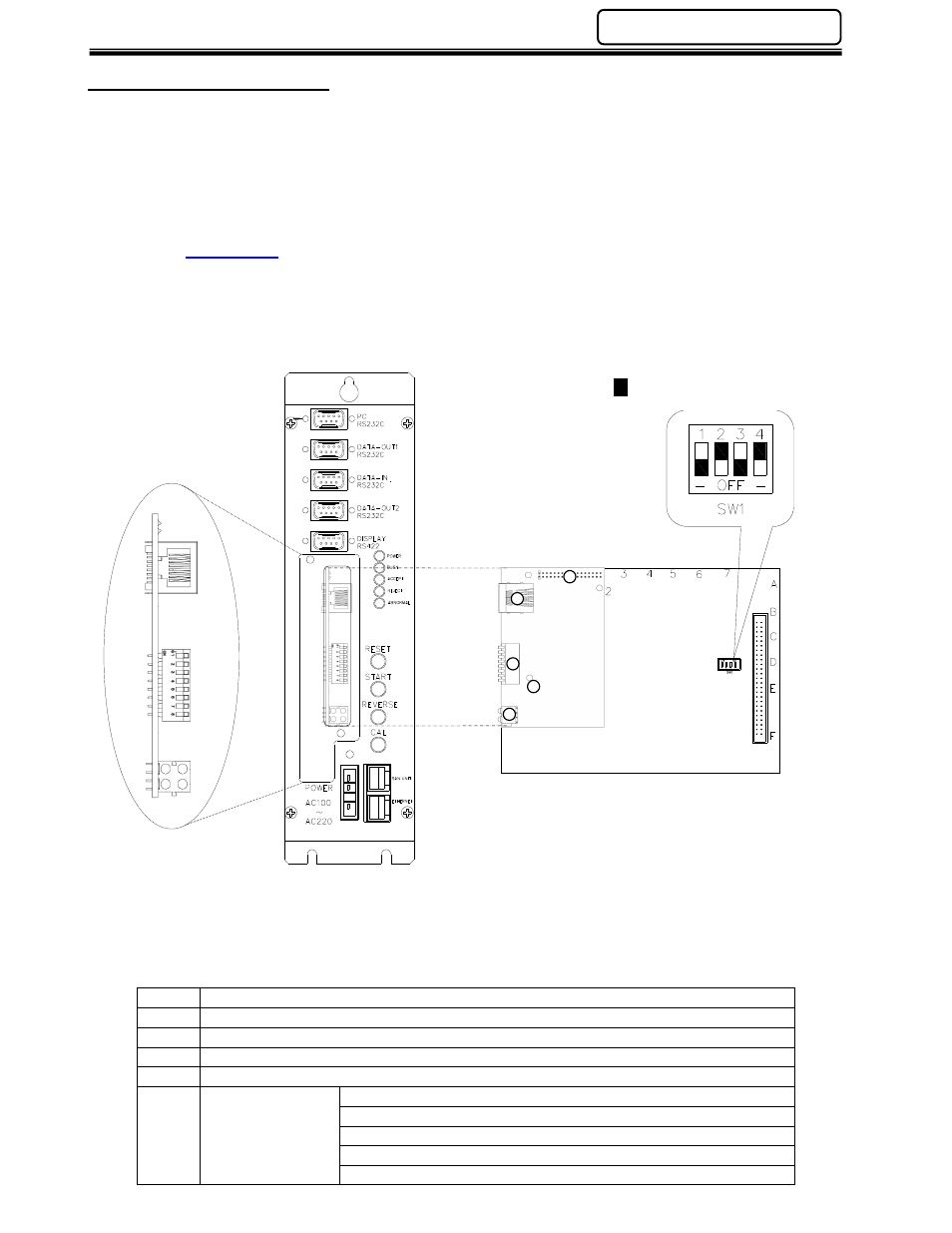
5.11 Ethernet-I/P Interface
The Ethernet-I/P communication interface allows slave connection to PLC networks that support
Ethernet communication via TCP/IP.
Maximum I/O data is 256 input bits & 256 output bits. FEC Inputs match the discrete input layout. FEC
Output location is programmed using the AFC User Console Software. Communication speeds of
10/100M baud (auto-selectable) are supported.
FEC integrates the Ethernet-I/P board manufactured by HMS Fieldbus Systems AB into the Multi-2
Unit’s modular I/O board. For further technical information on the Ethernet-I/P interface go to the HMS
website. (
www.hms.se
)
Item
Description
1
Application Connector
2
Ethernet Connector
3
Configuration Switches
4
Status LEDs (4)
5
Watchdog LED
Red - (flashing @ 2Hz) - ASIC and FLASH ROM check fault.
Green (flashing @ 2Hz) - module not initialized.
Green (flashing @ 1Hz) - module initialized and running OK.
Red (flashing @ 1Hz) - RAM check fault.
Red (flashing @ 4Hz) - DPRAM check fault.
2
1
3
4
5
- Represents switch position