FEC AFC1500 User Manual
Page 55
AFC1500 Multi-2 Unit Hardware Manual (Rev2.1)
5.4 Interbus S
®
Interface
InterBus S from Phoenix Contact is a
transmitted in frames that provide simultaneous and predictable updates to all devices in the network.
This interface board (S - version) has up to 512 bytes of assigned input data and 512 bytes of assigned
output data* (64bytes default). The 64 bytes of assigned I/O data allow a maximum of 512 inputs and
512 outputs per node. FEC I/O is assigned to the I/O points in these data are
designated spare). FEC Inputs match the
using the AFC User Console Software.
* When using Master boards where the PCP channel is NOT supported, the maximum number of I/O
will be 20 input bytes and 20 output bytes.
FEC integrates the Interbus S board manufactured by HMS Fieldbus Systems AB into the Multi
modular I/O board. For further technical information on the Interbus
(www.hms.se)
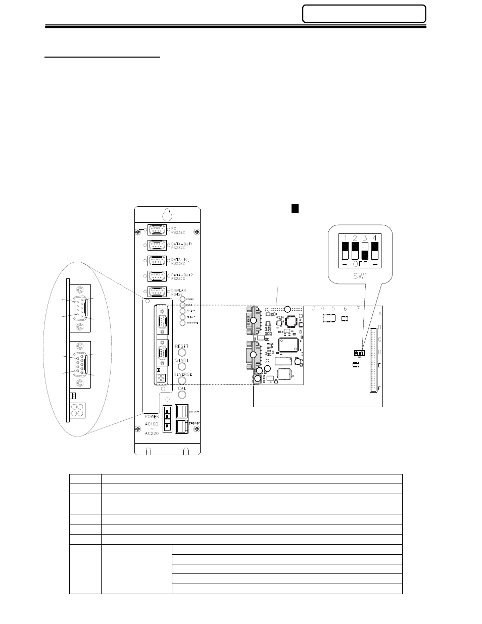
Item
1
Application Connector
2
BUS-IN Connector
3
BUS-OUT Connector
4
Baud Rate Jumper
5
Status LEDs (4)
6
UL LED - Green if voltage is OK at Bus
7
Watchdog LED
Re
Green (flashing @
Green (flashing @
Red
Red
5
1
5
1
6
9
9
6
1
2
3
4
2 Unit Hardware Manual (Rev2.1)
PAGE 5 - 11
Chapter 5: Control Interfaces
InterBus S from Phoenix Contact is an open-ring based, distributed device I/O network. I/O data is
transmitted in frames that provide simultaneous and predictable updates to all devices in the network.
version) has up to 512 bytes of assigned input data and 512 bytes of assigned
output data* (64bytes default). The 64 bytes of assigned I/O data allow a maximum of 512 inputs and
512 outputs per node. FEC I/O is assigned to the I/O points in these data areas (some I/O will be
designated spare). FEC Inputs match the discrete input layout. FEC Output locations are
using the AFC User Console Software.
* When using Master boards where the PCP channel is NOT supported, the maximum number of I/O
20 output bytes.
S board manufactured by HMS Fieldbus Systems AB into the Multi
modular I/O board. For further technical information on the Interbus S interface go to the HMS website.
Description
Application Connector
OUT Connector
Green if voltage is OK at Bus
Red - (flashing @ 2Hz) - ASIC and FLASH ROM check fault.
Green (flashing @ 2Hz) - module not initialized.
Green (flashing @ 1Hz) - module initialized and running OK.
Red (flashing @ 1Hz) - RAM check fault.
Red (flashing @ 4Hz) - DPRAM check fault.
Daughter board
2
1
3
4
5
6
7
- Represents switch position
Control Interfaces
based, distributed device I/O network. I/O data is
transmitted in frames that provide simultaneous and predictable updates to all devices in the network.
version) has up to 512 bytes of assigned input data and 512 bytes of assigned
output data* (64bytes default). The 64 bytes of assigned I/O data allow a maximum of 512 inputs and
as (some I/O will be
locations are programmed
* When using Master boards where the PCP channel is NOT supported, the maximum number of I/O
S board manufactured by HMS Fieldbus Systems AB into the Multi-2 Unit
S interface go to the HMS website.
ASIC and FLASH ROM check fault.
module initialized and running OK.
presents switch position