FEC AFC1500 User Manual
Page 95
AFC1500 Multi-2 Unit Hardware Manual (Rev2.1)
PAGE 5 - 51
Chapter 5: Control Interfaces
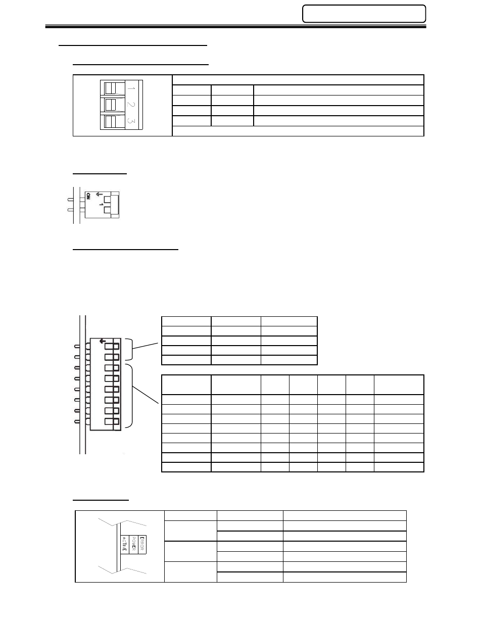
5.10.1 Component Descriptions
Fieldbus Interface Connection
Pin No.
Color
Description
1
Blue
COM Line
2
Clear
Ground
3
Shield
COM Line
Termination
Termination of the RIO network requires a terminating resistor at each end of the
network. A termination switch is provided on the front of the interface board. Set the
switch to “ON”, if termination is required. If external terminators are used, the switch
must be in the off position.
Configuration Switches
On an A-B Remote I/O network, each node must be assigned its own unique Rack Address. The
Rack Address is a value between 0 and 59 used to identify each node. The Rack Address and Baud
Rate are set using the DIP switches on the front of the module.
These switches must be set before power is on and cannot be changed during operation.
Baud Rate Settings
Baud Rate
SW-1
SW-2
57.6K
OFF
OFF
115K
ON
OFF
230K
OFF
ON
Reserved
ON
ON
Rack Address Settings
Rack
Address
SW-3
(MSB)
SW-4 SW-5 SW-6 SW-7
SW-8
(LSB)
Address 0
OFF
OFF
OFF
OFF
OFF
OFF
Address 1
ON
OFF
OFF
OFF
OFF
OFF
Address 2
OFF
ON
OFF
OFF
OFF
OFF
Address 3
ON
ON
OFF
OFF
OFF
OFF
…
…
…
…
…
…
…
Address 57
ON
OFF
OFF
ON
ON
ON
Address 58
OFF
ON
OFF
ON
ON
ON
Address 59
ON
ON
OFF
ON
ON
ON
Status LEDs
LED
State
Description
Error
OFF
Normal Operation
ON - Red
Bus off / Error
Active
OFF
No Communication
ON - Green
Communication Active
Power
OFF
Power Off
ON - Green
Power On
ON
8
5
4
2
3
7
6
1