FEC AFC1500 User Manual
Page 46
AFC1500 Multi-2 Unit Hardware Manual (Rev2.1)
PAGE 5 - 2
Chapter 5: Control Interfaces
5.1 I/O Interface Board
The Multi-2 unit interface board provides the interface between real world control signals and the
AFC1500 Fastening system I/O. Since there are many different I/O control structures in the industry
today, the Multi-2 unit has the ability to adapt to these through use of the I/O interface board. The
interface is available in many Fieldbus or “open architecture” configurations as well as standard
hardwired discrete I/O.
The Multi-2 unit I/O assumes control of the individual SAN unit I/O, thus eliminating the need to wire to
each individual spindle.
All I/O interface motherboards have a DIP Switch SW1 (located at position 7D) which has to be
configured so the Multi-2 Unit can identify the type of interface installed. The table below identifies the
switch set-up for configurable interface boards.
Interface Type
SW1
1
SW1
2
SW1
3
SW1
4
Discrete I/O (Sink Type – active true low )
ON
OFF
OFF
OFF
Discrete I/O (Source Type – active true high)
OFF
ON
OFF
OFF
DeviceNet-S
®
(for Toolsnet
®
)
ON
ON
OFF
OFF
Profinet IO
OFF
OFF
ON
OFF
Interbus-S
®
(for Toolsnet
®
)
ON
OFF
ON
OFF
Allen Bradley Remote I/O
OFF
ON
ON
OFF
Profibus
®
(for Toolsnet
®
)
ON
ON
ON
OFF
Modbus Plus
®
OFF
OFF
OFF
ON
DeviceNet-S
®
ON
OFF
OFF
ON
Ethernet I/P
OFF
ON
OFF
ON
Interbus-S
®
ON
ON
OFF
ON
Mitsubishi CC-Link
®
Version 2 (I/O & Messaging)
OFF
OFF
ON
ON
Profibus
®
ON
OFF
ON
ON
Mitsubishi CC-Link
®
Version 1 (I/O only)
OFF
ON
ON
ON
M-Net
ON
ON
ON
ON
(Other interfaces available, contact FEC)
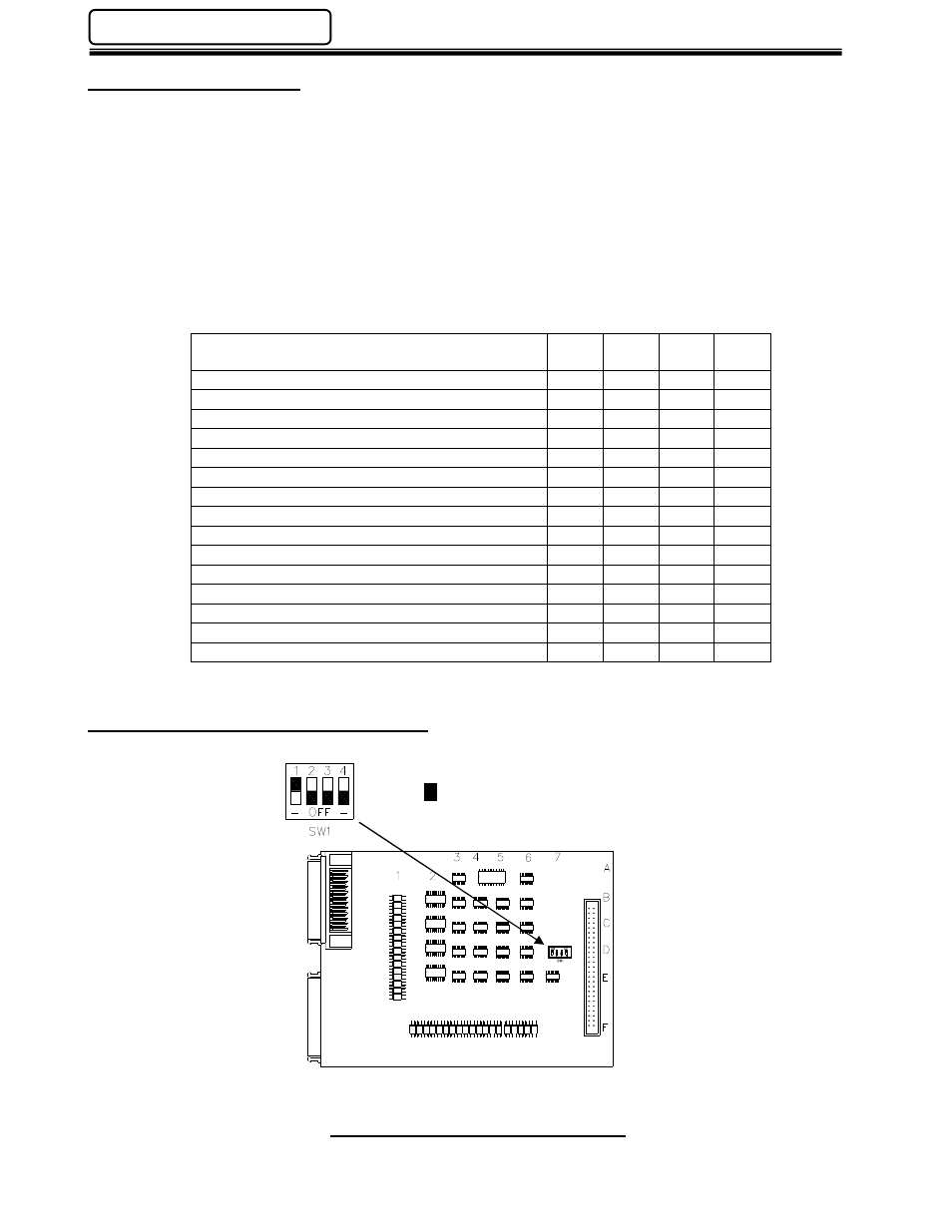
5.2 Interface Board DIP Switch Setup
Throughout this chapter, SW1 settings will be represented as follows:
Side View
–––– I/O Interface Circuit Board
- Represents switch position