FEC AFC1500 User Manual
Page 87
AFC1500 Multi-2 Unit Hardware Manual (Rev2.1)
PAGE 5 - 43
Chapter 5: Control Interfaces
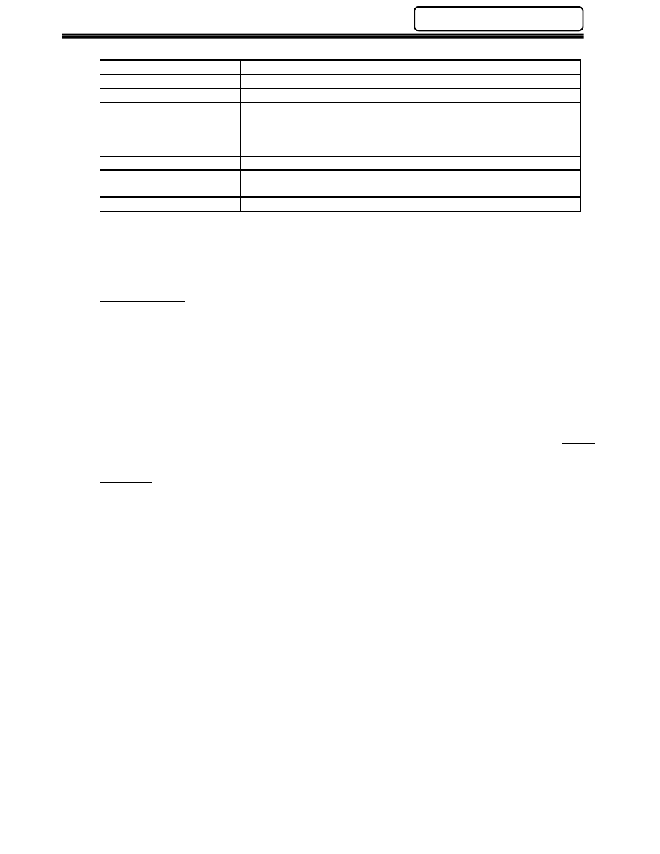
CC-Link Specifications
Speed
156K - 10M baud - selectable
Stations
64 Max.
Distance
1200m max. at 156K baud / 50m max. at 10Mbit/s
Cable
Shielded Copper Twisted Pair
Mitsubishi BA1SJ61-(m) m=Meters
Belden 8102 or equivalent
Communications Type
Master/Slave - EIA RS485
Transmission Format
HDLC Standard
Maximum Cyclic I/O Size
896 inputs, 896 outputs max. Size set in groups of 256 I/O
(Occupied Stations)
I/O Configuration*
I/O addressing set by PLC TO / FROM commands in Logic
* Actual I/O addressing must be assigned in the PLC logic. See the Mitsubishi User Manual #
13J872 Control & Communication - Link System Master / Local Module for logic reference. (Ref.
Section 10)
Configuration
Configuration of the CC-Link system is done in the PLC Logic. It is essential that this configuration
matches the Dip Switch settings of the FEC CC-Link slave. FEC is considered a “
Remote Device”
in the PLC configuration. The number of “Occupied Stations” set in the PLC must also match the
settings in the AFC User Console set-up.
(Note: The last 16 output addresses are used by the
CC-Link communication & cannot be used by the user)
FEC CC-Link (Version 2) I/O configuration is programmable using the AFC User Console software.
I/O can be set as required by the application according to parameter limits set forth by the CC-Link
System Profile (CSP file). The AFC Software allows configuration of the number of Occupied
Stations and Extended Cyclic Settings in the Multi Unit. Configuration of the CC-Link Master MUST
match the configuration of the FEC CC-Link slave.
CSP File
To simplify network configuration, CC-Link devices may be associated with a CC-Link System
Profile, also known as a CSP-file. This file contains a description of the device and can be used by
some CC-Link system utilities to simplify the configuration process.
The CSP file associated with the FEC device can be downloaded directly from HMS - www.hms.se.