FEC AFC1500 User Manual
Page 106
AFC1500 Multi-2 Unit Hardware Manual (Rev2.1)
PAGE 5 - 62
Chapter 5: Control Interfaces
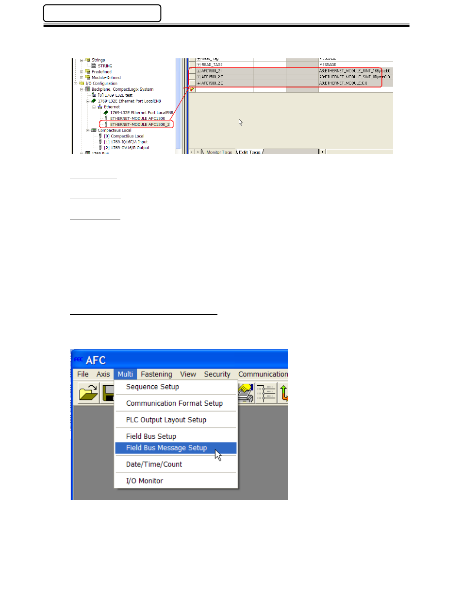
When the MULTI-2 unit is added to the I/O configuration, the data table will be added to the
controller tags automatically.
AFC1500_2:I
Input signals from MULTI-2 unit. (MULTI-2 -> PLC)
AFC1500_2:O
Output signals to MULTI-2 unit (PLC -> MULTI-2)
AFC1500_2:C
Message communication data from the MULTI-2 unit (MULTI-2 -> PLC for fastening result data).
An additional program/command needs to be added for retrieving the data.
2. Set up the Multi-2 Unit’s Fieldbus Message to transfer data using the MSG function.
Before the MESSAGE function can be setup to transfer data, the AFC1500 Software first must
be configure for the data type and format of the data to be transferred to the PLC.
AFC1500 Fieldbus Message Setup
Configure the field bus message through the AFC User Console software by selecting “Field Bus
Message Setup” from the “Multi” pulldown menu.