FEC AFC1500 User Manual
Page 75
AFC1500 Multi-2 Unit Hardware Manual (Rev2.1)
PAGE 5 - 31
Chapter 5: Control Interfaces
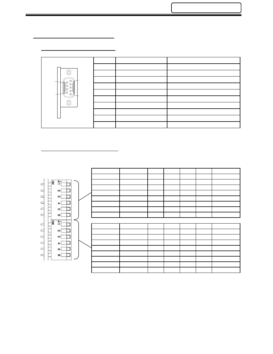
5.7.1 Component Descriptions
Fieldbus Interface Connector
Pin No.
Signal
Description
Housing PE
Protective Earth Ground
1
Shield
Cable Shield
2
MBP Line B
Modbus Plus Line B
3
MBP Line A
Modbus Plus Line A
4
NC
-
5
NC
-
6
NC
-
7
NC
-
8
NC
-
(9 pin female D-sub)
9
NC
-
Node ID & Source ID Switches
(S1) Node ID Settings
Function
SW-1
(MSB)
SW-2 SW-3 SW-4 SW-5
SW-6
(LSB)
Address 1
ON
ON
ON
ON
ON
ON
Address 2
ON
ON
ON
ON
ON
OFF
Address 3
ON
ON
ON
ON
OFF
ON
Address 4
ON
ON
ON
ON
OFF
OFF
…
…
…
…
…
…
…
Address 62
OFF
OFF
OFF
OFF
ON
OFF
Address 63
OFF
OFF
OFF
OFF
OFF
ON
Address 64
OFF
OFF
OFF
OFF
OFF
OFF
(S2) Source ID Settings
Function
SW-1
(MSB)
SW-2 SW-3 SW-4 SW-5
SW-6
(LSB)
Address 1
ON
ON
ON
ON
ON
ON
Address 2
ON
ON
ON
ON
ON
OFF
Address 3
ON
ON
ON
ON
OFF
ON
Address 4
ON
ON
ON
ON
OFF
OFF
…
…
…
…
…
…
…
Address 62
OFF
OFF
OFF
OFF
ON
OFF
Address 63
OFF
OFF
OFF
OFF
OFF
ON
Address 64
OFF
OFF
OFF
OFF
OFF
OFF
S1 and S2 settings must be made before power is on and cannot be changed during
operation.
5
1
9
6