9 cc-link, Interface (version 2) – FEC AFC1500 User Manual
Page 86
AFC1500 Multi-2 Unit Hardware Manual (Rev2.1)
PAGE 5 - 42
Chapter 5: Control Interfaces
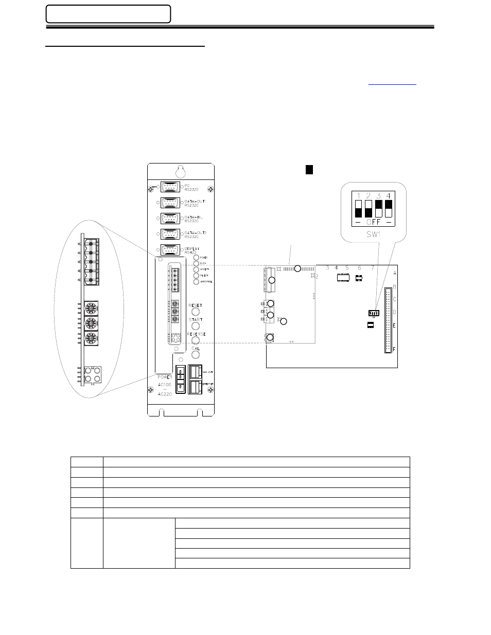
5.9 CC-Link
®
Interface (Version 2)
FEC integrates the CC-Link board (Version 2 setting) manufactured by HMS Fieldbus Systems AB into
the Multi-2 Unit’s modular I/O board when CC-link must send both I/O and Message Data. For further
technical information on the CC-Link (Version 2) interface go to the HMS website. (
www.hms.se
)
NOTE: The FEC CC-Link (V2) module is configured as a “
Remote Device Station” when setting up the
parameters in the PLC program.
For detailed information on the Mitsubishi CC-Link Network, see the Mitsubishi User Manual # 13J872
Control & Communication - Link System Master / Local Module.
Item
Description
1
Application Connector
2
CC-Link Connector
3
Baud Rate Setting Switch
4
Station Number Setting Switches (2)
5
Status LEDs (4)
6
Watchdog LED
Red - (flashing @ 2Hz) - ASIC and FLASH ROM check fault.
Green (flashing @ 2Hz) - module not initialized.
Green (flashing @ 1Hz) - module initialized and running OK.
Red (flashing @ 1Hz) - RAM check fault.
Red (flashing @ 4Hz) - DPRAM check fault.
Daughter board
3
2
5
1
6
4
- Represents switch position