FEC AFC1500 User Manual
Page 41
AFC1500 Multi-2 Unit Hardware Manual (Rev. 2)
PAGE 4 - 17
Chapter 4: Installation & Wiring
(Output Signals – Continued)
In addition to the main Multi unit output signals, individual spindles that are connected to the Multi unit
report status signals to the Multi Unit. These signals are available on a “per spindle” basis and can
be used or programmed using the AFC User Console software.
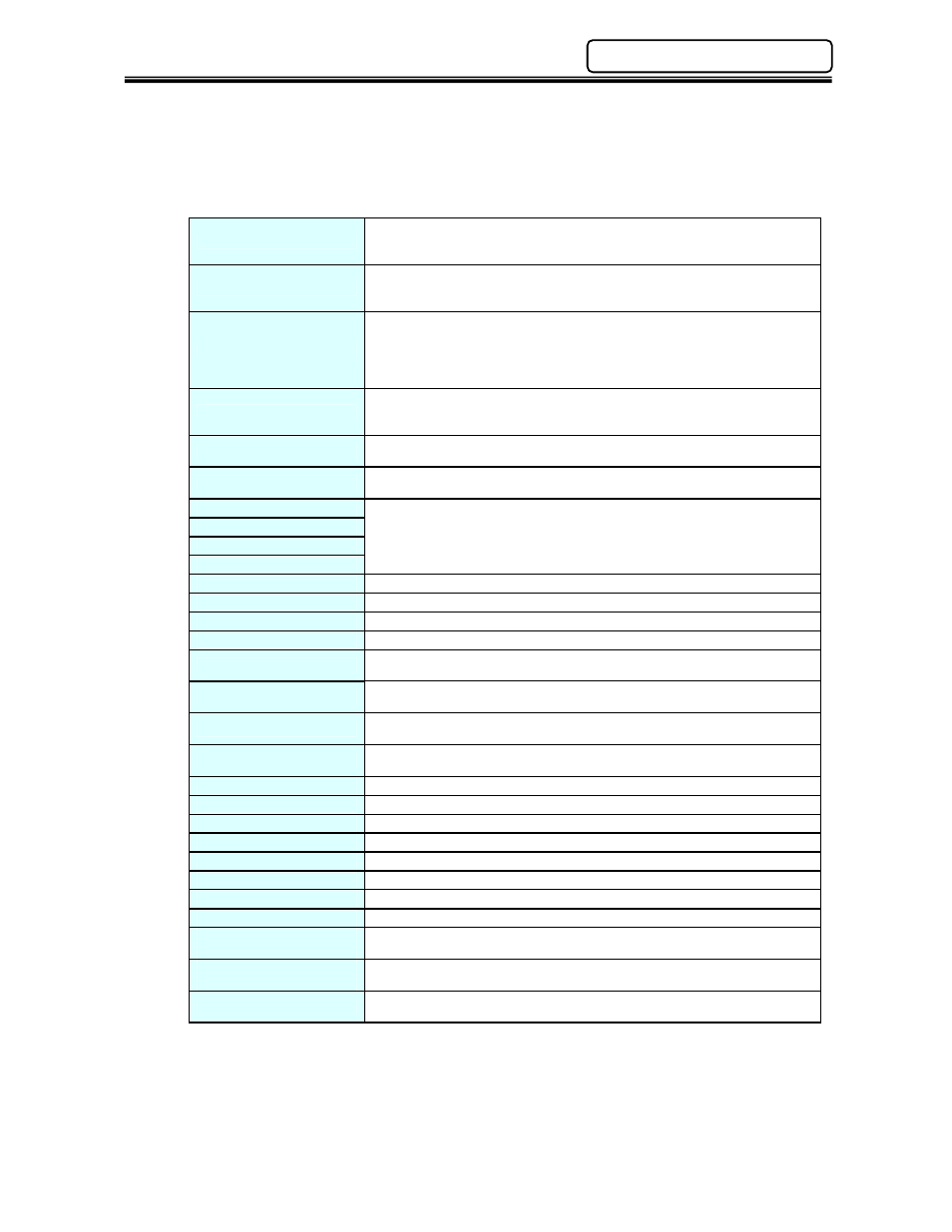
Available Individual Spindle Unit Output Signals (Per connected spindle)
Reject
Output when the fastening result is a REJECT. Indicates that the spindle has
failed achieving the fastening limits. This output remains active until the
START signal or RESET signal is input.
Accept
Output when the fastening result is an ACCEPT. Indicates that the spindle is
within fastening limits. This output remains active until the START signal or
RESET signal is input.
Abnormal
Output when an Abnormal condition occurs. This signal indicates that the
spindle has detected an internal fault and can no longer proceed. The fault
maybe generated during a self-check function (see AFC1500 Operation
Manual for troubleshooting). The RESET signal clears the abnormal
condition.
Ready
Output when the spindle is in the READY condition. Indicates spindle is
ready to operate and inputs are enabled. This signal is inactive (off) when the
BUSY output is active (on).
Busy
Output after a START signal is received, and remains active until the
fastening cycle is complete and the READY signal is output.
Bypass
Signal is active when the spindle is bypassed either from San Unit bypass
input signal or from the San Unit bypass switch.
Parameter Select 1
Output confirmation of PARAMETER SELECT 1~4 input selections.
Parameter Select bits are active according to what sequence is set from the
sequence select inputs.
Parameter Select 2
Parameter Select 3
Parameter Select 4
Time 1 Low Reject
Output when 1
st
Time result is below the set 1
st
Time Low Limit value.
Time 1 High Reject
Output when 1
st
Time result is above the set 1
st
Time High Limit value.
Time 2 Low Reject
Output when Final Time result is below the set Final Time Low Limit value.
Time 2 High Reject
Output when Final Time result is above the set Final Time High Limit value.
Peak Torque Low Reject
Output when Peak Torque result is below the set Peak Torque Low Limit
value.
Peak Torque High Reject
Output when Peak Torque result is above the set Peak Torque High Limit
value.
Final Torque Low Reject
Output when Final Torque result is below the set Final Torque Low Limit
value.
Final Torque High Reject
Output when Final Torque result is above the set Final Torque High Limit
value.
Angle Low Reject
Output when Angle result is below the set Angle Low Limit value.
Angle Low Reject
Output when Angle result is above the set Angle High Limit value.
Rate 1 Low Reject
Output when Rate 1 result is below the set Rate 1 Low.
Rate 1 High Reject
Output when Rate 1 result is above the set Rate 1 High.
Rate 2 Low Reject
Output when Rate 2 result is below the set Rate 2 Low.
Rate 2 High Reject
Output when Rate 2 result is above the set Rate 2 High.
Rate 3 Low Reject
Output when Rate 3 result is below the set Rate 3 Low.
Rate 3 High Reject
Output when Rate 3 result is above the set Rate 3 High.
Current Limit Low
Warning
Output when the current is below acceptable Limits.
Current Limit High
Warning
Output when the current is above acceptable Limits.
Combination Bits 1-8
Used to create “special” outputs formed by using a combination of SAN Unit
outputs in “AND / OR” logic.