4 signal timing chart, Signal timing, Chapter 4: installation & wiring – FEC AFC1500 User Manual
Page 42: Stop, Ready, Reset, Reverse, Start, Fastening, Fastening operation fastening operation
AFC1500 Multi-2 Unit Hardware Manual (Rev. 2)
PAGE 4 - 18
Chapter 4: Installation & Wiring
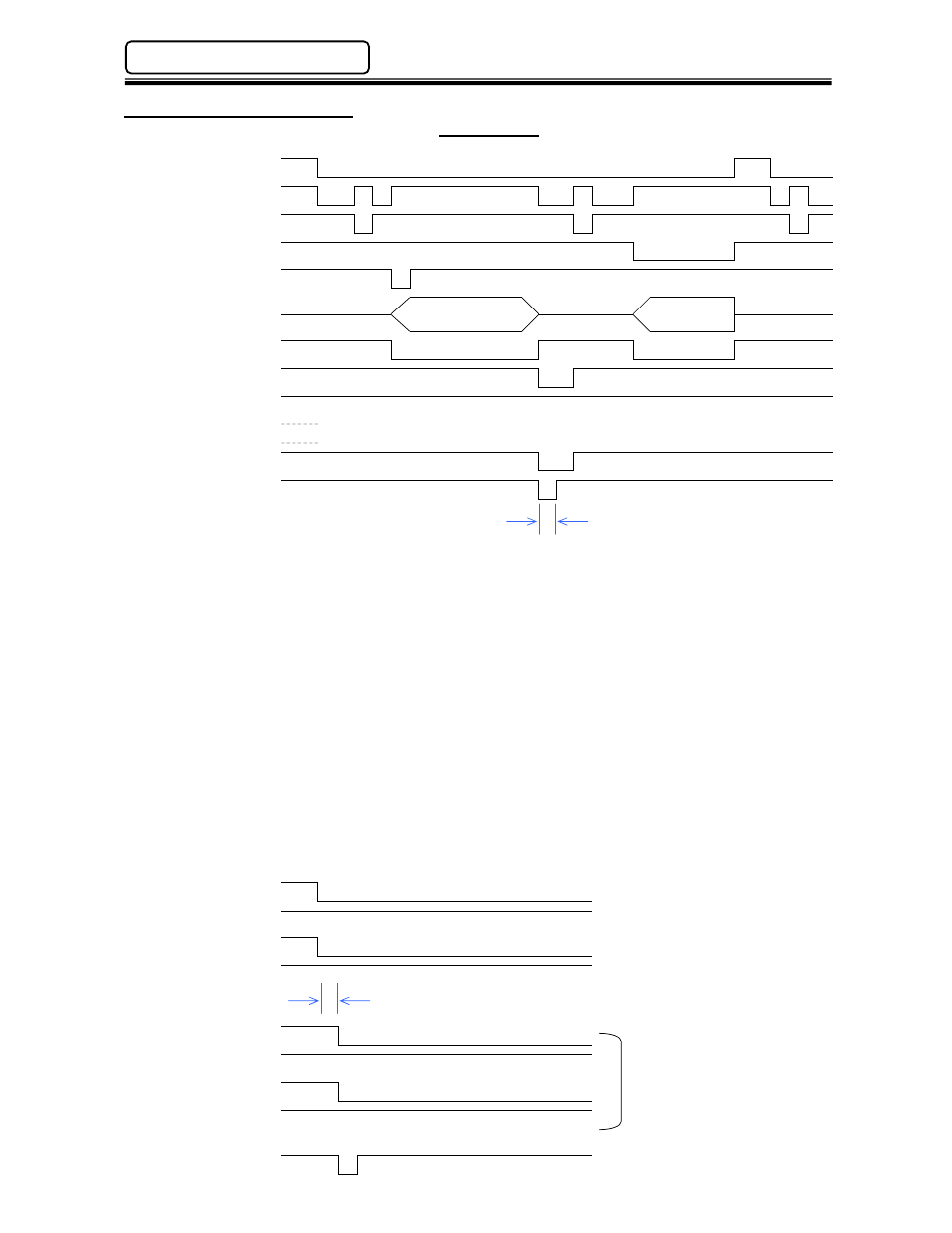
4.7.4 Signal Timing Chart
Signal Timing
STOP
OFF
ON
READY
OFF
ON
RESET
OFF
A
ON
REVERSE
START
OFF
A
ON
FASTENING
Fastening
Operation
Fastening
Operation
BUSY
OFF
ON
ACCEPT
OFF
ON
REJECT
OFF
ON
ABNORMAL
OFF
ON
END
OFF
ON
COUNT UP
OFF
A
ON
Because the RESET input clears all fastening data and discrete outputs, it should only be activated
to clear a system Abnormal or to perform a Zero Level Check. The system will automatically reset
with each fastening start. A manual RESET activation between cycles could result in data loss.
The REVERSE signal must be maintained for the duration of the desired REVERSE function.
The STOP input is normally closed and enables all other functions. When open (OFF), all
operations cease and all inputs / outputs become inactive.
The START signal will not operate during RESET, REVERSE or ABNORMAL signal activation. A
pulse of 200~500 milliseconds is required for AUTO START mode. For DEADMAN mode (Used
mainly in handheld applications), the signal must be maintained for the complete fastening cycle
(until BUSY goes low).
When the ABNORMAL signal is activated, the system must be RESET before normal operation will
resume.
REJECT & ACCEPT signals are maintained until the start of the next cycle or on a RESET.
READY indicates when the system is ready to start.
It is recommended when changing sequences that the Sequence Select outputs be used to verify
that the sequence has been changed before issuing a start signal. Delay from Sequence Select
input to Sequence Select output is approximately 5ms.
Seq. Sel. Bit 0
OFF
ON
Seq. Sel. Bit 1
OFF
ON
Seq. Sel. Bit 2
OFF
ON
Seq. Sel. Bit 3
OFF
ON
Bit 0 Selected
OFF
ON
Bit 1 Selected
OFF
ON
Bit 2 Selected
OFF
ON
Bit 3 Selected
OFF
ON
START
OFF
ON
200 ~ 500ms (A)
Allow 20ms to interlock the Sequence Select
Command and the associated result signal.
Sequence Select No. 6
(Multi-2 Inputs)
Sequence No. 6 Selected
(Multi-2 Outputs)
* No bit selected = Sequence No. 1