FEC AFC1500 User Manual
Page 114
AFC1500 Multi-2 Unit Hardware Manual (Rev2.1)
PAGE 5 - 70
Chapter 5: Control Interfaces
5.12.1 Component Descriptions
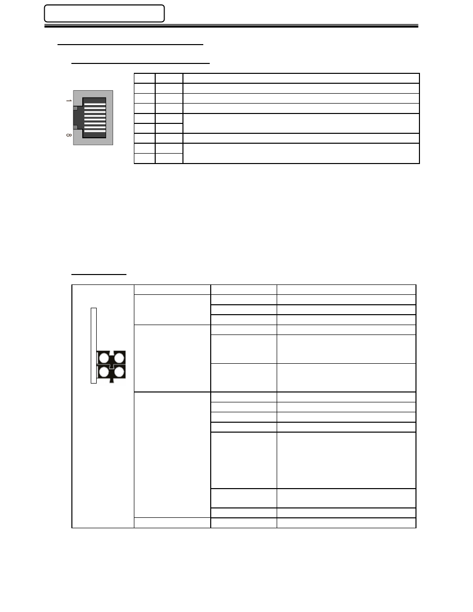
Fieldbus Interface Connections
Pin Signal
Note
1
TD+
2
TD-
3
RD+
4
-
Normally left unused; to ensure signal integrity, these pins are tied
together and terminated to PE via a filter circuit in the module.
5
-
6
RD-
7
-
Normally left unused; to ensure signal integrity, these pins are tied
together and terminated to PE via a filter circuit in the module.
8
-
Status LEDs
LED
State
Description
1 – Link/Activity
Green
Link Established
Green, Flashing
Receiving/Transmitting data
Off
No Link Established or power off
2 - Communication
Status
Off
Offline
Green solid
Online, Run
-
Connection established
-
IO controller in RUN
Green, 1 flash
Online, Stop
-
Connection Established
-
IO controller in STOP
3 - Module Status
Off
No power or not initialized
Green solid
Initialized, no error
Green, 1 flash
Diagnostic data available
Green, 2 flashes Blink. Factory ID tool
Red, 1 flash
Configuration Error
-
Too many modules
-
I/O from IO controller config.
Too large
-
Configuration Mismatch (no
module, wrong module)
Red 3 flashes
No station name or no IP address
assigned
Red, 4 flashes
Internal error
4 – Not Used
1
2
3
4