3 input signals (plc-in) connector – FEC AFC1500 User Manual
Page 51
AFC1500 Multi-2 Unit Hardware Manual (Rev2.1)
PAGE 5 - 7
Chapter 5: Control Interfaces
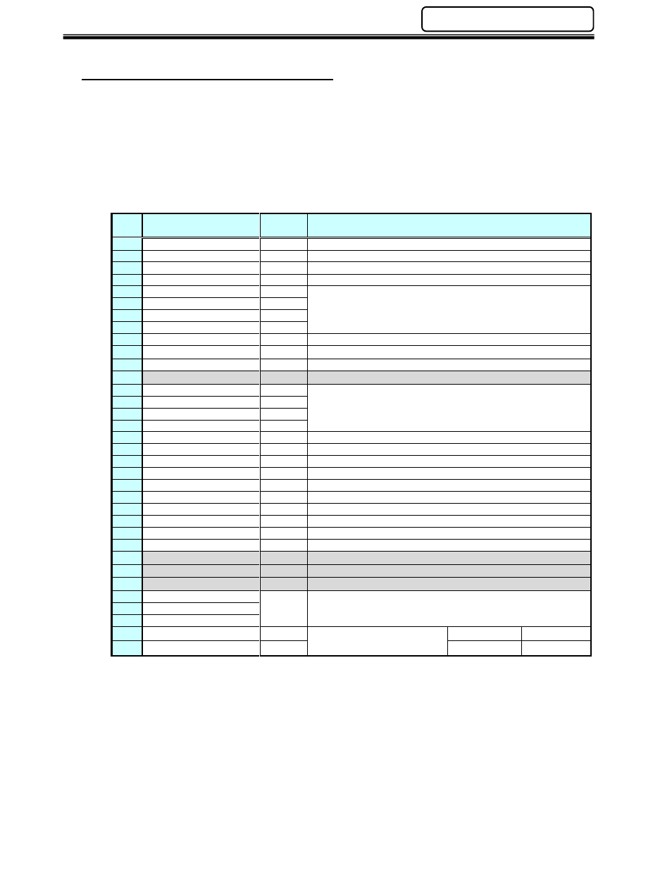
5.3.3 Input Signals (PLC-IN) Connector
The Input Signals are provided on the PLC IN connector. Inputs are assigned in the order as
shown in the table below and cannot be changed. Pins designated as “Not Used” have no input
assigned to them.
NOTE: When using Discrete I/O, “Bypass Spindle” input signals assigned to the PLC IN
connector can only be used for up to 10 individual Spindles (from the Multi-2 Unit). When using
Discrete I/O and you desire to connect this signal from additional spindles, the signal must be
wired from the individual SAN Controllers using the SAN Unit’s PLC connector. (An alternative to
this is to use a fieldbus interface which has control of all spindle bypass signals from the
interface.)
Pin#
Signal
Contac
t
Description
1
Emergency Stop
N.C.
Emergency Stop Input
2
Reset
N.O.
Reset Input
3
Reverse
N.O.
Reverse Spindle Rotation Input
4
Start
N.O.
Start Cycle Input
5
Sequence Select 0
N.O.
Sequence Select Input
6
Sequence Select 1
N.O.
7
Sequence Select 2
N.O.
8
Sequence Select 3
N.O.
9
Cycle Count Up
N.O.
Cycle Count Input
10
Cycle Count Clear
N.O.
11
Self Check Disable
N.O.
Disables automatic self check
12
Not Used
13
IN PORT 1
N.O.
External Sequence interface Input
14
IN PORT 2
N.O.
15
IN PORT 3
N.O.
16
IN PORT 4
N.O.
17
BYPASS Spindle No.1
N.O.
Bypass’s spindle #1
18
BYPASS Spindle No.2
N.O.
Bypass’s spindle #2
19
BYPASS Spindle No.3
N.O.
Bypass’s spindle #3
20
BYPASS Spindle No.4
N.O.
Bypass’s spindle #4
21
BYPASS Spindle No.5
N.O.
Bypass’s spindle #5
22
BYPASS Spindle No.6
N.O.
Bypass’s spindle #6
23
BYPASS Spindle No.7
N.O.
Bypass’s spindle #7
24
BYPASS Spindle No.8
N.O.
Bypass’s spindle #8
25
BYPASS Spindle No.9
N.O.
Bypass’s spindle #9
26
BYPASS Spindle No.10
N.O.
Bypass’s spindle #10
27
Not Used
28
Not Used
29
Not Used
30
Data Select 0
Output Data Bank Select inputs
31
Data Select 1
N.O.
32
Data Select 2
33
Input Signal Power
Common for input signal.
Sink Type
+24V
34
Input Signal Power
Source Type
+0V
Note) NC: Normal Closed, NO: Normal Open
For Input Signal definition see Section 4.7.2.