Micromod MOD: 30ML Operation and Template Setup User Manual
Page 8
MOD 30ML Operation
INTRODUCTION
1-2
redundant, removable non-volatile RAM which backs up the configured database and, if left
on the instrument during operation, current process data. Nonvolatile RAM memory has a
typical data retention of 10 years.
1.2.2 Configuration
Configuration of the instrument is accomplished via one of two methods. For applications
using single loop PID, single station cascade, feedforward and ratio/bias, canned strategies
and their faceplates are easily implemented through the instruments front face displays and
operator push buttons. Template configuration uses easy-to-read English prompts.
For more complex applications, beyond those offered with the basic instrument, configuration
is accomplished through the icon-based Application Builder Software which is used to create,
edit, save, download and document the data base in a graphic environment. Downloading
instrument configurations can be done via ICN, or via Modbus over RS-232 or a 4-wire RS-
485 network. This software is also used to prepare runtime operation files for a computer
using the ICN or Modbus protocol. Local display and operations can also be provided using
the 2021W Local Control Panel over the ICN.
1.2.3 Operation
The instrument can display and control a variety of process variables such as temperature,
pressure, flow, and liquid level. In addition to continuous display of the process variable for a
selected loop, the front panel display shows the operating set-point, control output, process
alarm indication, loop tag name, and status indication of control mode and set-point source.
Front panel keys provide for operational activities such as auto/manual switching,
remote/local set-point switching, manual output adjustment, process alarm and diagnostic
message acknowledgment, and enabling communication with a host device.
1.2.4 Process I/O
Two isolated universal analog inputs and two current outputs
are standard. Each analog input can receive direct connection
of either milliamp (2-wire or non 2-wire), millivolt, volt, RTD
thermocouple or resistance. Inputs have full galvanic
isolation. Both analog outputs can be user set between span
limits of 0 and 50 milliamps.
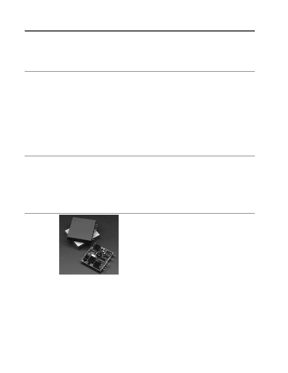
In addition there can be up to eleven process I/O and
communication modules. Plug in modules include various
types of analog input, analog output, digital input, digital
output, Instrument Communication Network (ICN) and
MODBUS
serial communications. Signal conditioning, fail-safe and power fail/recovery parameters may
reside in each individual module.
Analog I/O Modules
Analog input modules provide high-resolution signal conditioning performed in the module.
Process signals including RTD and thermocouple are connected directly to the rear terminations
without requiring transmitters or transducers for signal conversion. A single module supports all
thermocouple types with upscale burnout detection. Cold junction compensation is also provided.
One current input module type supplies isolated loop power for 2-wire transmitters. Other input
types include volt, millivolt, 2- and 3-wire RTD with upscale burnout detection and current input