Limit switches – FlexLink Elevator Руководство пользователя User Manual
Page 62
Installation and adjustment
54
5112204
Interlocking sensors
The light beam of the photo-electric sensor should hit the reflector. The lift
cage should not act as obstacle at any height.
5.5.6.2.2
Adjustment
The sensor is adjusted so that the XT conveyers stops within the area, lim-
ited by the two photo-electric laser cells (WL9L).
5.5.6.3
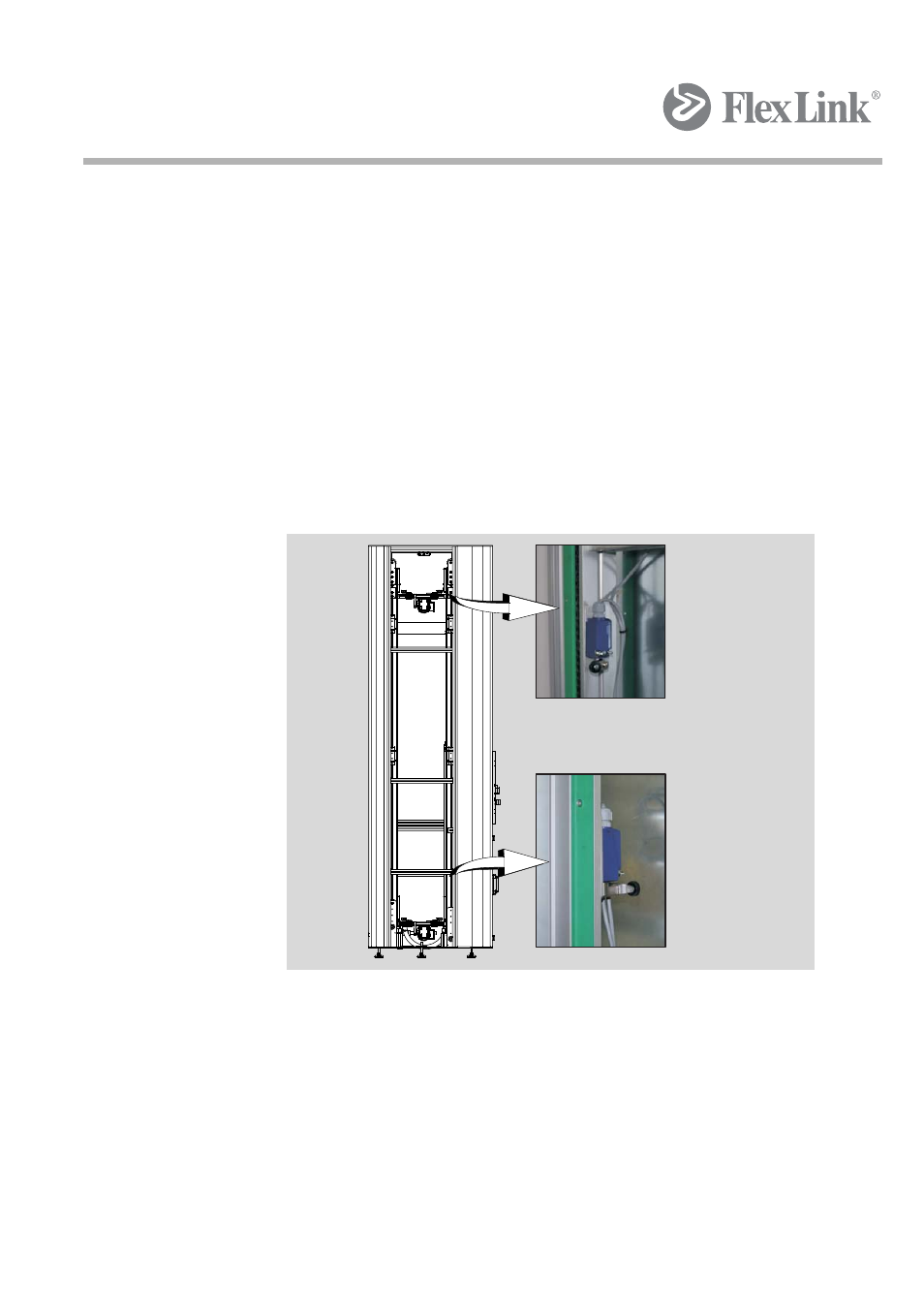
Limit switches
This does not apply to RTI units. These should be protected by the appli-
cation.
Figure 30 Limit switches
The limit switches are located in the upper and lower parts of the frame and
are activated in the event of excessive lifting device travel.
Mechanical dampers serve as protection after the limit switches.
To assure correct operation of the elevator, ensure that the switches are
correctly positioned and are activated in the intended direction of travel.
- XC (44 мм) Монтаж (68 pages)
- XT (макс. 30 кг) Монтаж (74 pages)
- XT (макс. 30 кг) Тех. обслуживание (67 pages)
- XK (макс. 30 кг) Тех. обслуживание (19 pages)
- X300X (300 мм) Монтаж XBCCX (2 pages)
- X300X (300 мм) Монтаж опорного кронштейна (2 pages)
- X300X (300 мм) Монтаж стола (2 pages)
- X300X (300 мм) Монтаж соединительной скобы (2 pages)
- X300X (300 мм) Монтажный комплект (2 pages)
- X85Y (85 мм) Монтаж (2 pages)
- Блок очистки_сушки конвейера (2 pages)
- Блок очистки конвейера (2 pages)
- WL626 (626 мм) Монтаж (48 pages)
- XK (105 мм) Монтаж системы капельных поддонов (4 pages)
- XK (105 мм) Монтаж грипперных регулир. валов (1 page)
- XL (65 мм) Монтаж изогнутых профилей (4 pages)
- Laser Cell (1 page)
- Spiral Elevator (74 pages)
- AGS Монтаж (12 pages)
- Конвейерная цепь Монтаж (2 pages)
- Приспособление для сверления профиля Монтаж (2 pages)
- Направляющие и опорные салазки (пластик) Монтаж (8 pages)
- Направляющие и салазки (сталь) Монтаж (1 page)
- X85 Монтаж стальной цепи 5056849 (1 page)
- XB Монтаж (2 pages)
- XT Compact Монтаж (1 page)
- Фрикционная муфта (1 page)
- X45 Руководство пользователя (46 pages)
- X65 Функциональные модули Руководство пользователя (48 pages)
- X85 Туннельный модуль XBUL 11T Руководство пользователя (10 pages)
- X85 Индексирующий модуль XBUL 11Х Руководство пользователя (11 pages)
- X85 Основной модуль XBUL 11 Руководство пользователя (11 pages)
- X85 Промежуточный модуль распределения XBUТ 180С Руководство пользователя (9 pages)
- X85 Модуль комбинирования XBUТ 45СR,90CR,45CL,90CL Руководство пользователя (9 pages)
- X85 Модуль распределения XBUТ 45СR,90CR,45CL,90CL Руководство пользователя (9 pages)
- X85 Модуль объединения XBUТ 45СR,90CR,45CL,90CL Руководство пользователя (9 pages)
- XK Функциональные модули Руководство пользователя (44 pages)
- X65 Основной модуль XLUL 11 Руководство пользователя (30 pages)