15 ecm - apu control interface, Interconnection – Alpha Technologies AlphaGen 5.0kW Auxiliary Power Unit User Manual
Page 81
4. Interconnection
81
031-132-B0-001 Rev. A
TM
©2000
4.3
Connectors, continued
Pin Description
Function
1
+12V Ignition Battery
Ignition battery Fused 12V from APU
2
Neg Ignition Battery
Ignition Battery Negative from APU
3
Low Oil Pressure
Active LOW signal denotes Low Oil Pressure.
4
Over-Temp
Active LOW signal indicates Over-Temp.
5
Start Command
Active LOW from ECM activates APU START
relay.
6
Common (Start Stop)
Common return between Start and Stop relays.
7
Stop Command
Active LOW from ECM activates APU STOP
relay.
8
Over-Speed
Active LOW signal denotes engine RPM was
exceeded.
9
Over-Crank
Active LOW signal denotes Over Crank Limit is
reached.
10
Engine Run
Active LOW signal denotes the Engine is
running.
11
Not Used
12
Not Used
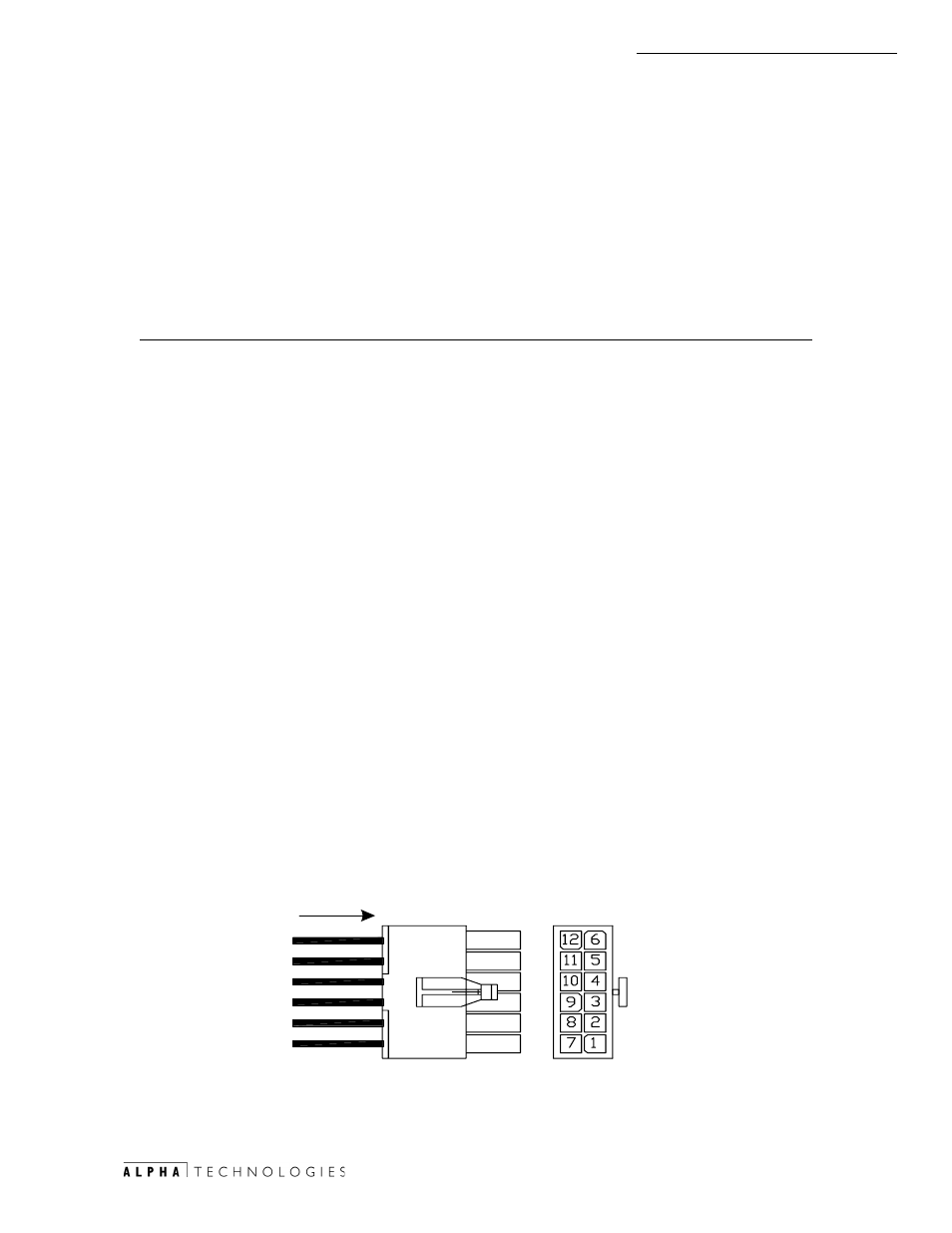
4.3.15 ECM - APU Control Interface
The interface control is a 12-pin (2x6 row) Mini Mate-N-Lok style connector.
See Fig. 4-9, item 12 for location.
E#
5($5
Г
9,(:
:,5(
Г
6,'(
5($5
9,(:
Fig.4-16 APU Control Interface
- AlphaCell GelCell Series (32 pages)
- FXM 650, 1100, 2000 UPS (96 pages)
- Cordex 48-1.2kW (68 pages)
- Radium MiniBay (57 pages)
- Fiber Backhaul Enclosure (FBE) (19 pages)
- FBE2322 Enclosure System (38 pages)
- FlexNet PMR, GMR Series (49 pages)
- Te25xh (38 pages)
- FlexNet MPS48-12M - Technical Manual (33 pages)
- FlexNet MPS48-12M - Quick Start Guide (2 pages)
- FlexNet ELPM 300-48D (25 pages)
- FlexNet FMPS (40 pages)
- FlexPoint AX Series (34 pages)
- FlexPoint FPR1207-F - Technical Manual (18 pages)
- FlexPoint FPR1207-F - Quick Start Guide (2 pages)
- AlphaGen PN-6x-T 7.5kW 48VDC - Installation and Operation Manual (79 pages)
- AlphaGen CE-3x2 5K-T 48Vdc (95 pages)
- AlphaGen PN-6x-T 7.5kW 48Vdc (95 pages)
- AlphaGen 3.5_5.0kW Kohler COM5 (80 pages)
- Security Bar Field For UPE-3, UPE-6, UPE-M3, UPE-M6, PN Series and CE Series (2 pages)
- AMPS80 HP (116 pages)
- 255A Bypass Switch (24 pages)
- AMP24 HP (108 pages)
- FXM350_Micro350 UPS (112 pages)
- CFR 600, CFR 600XT, CFR 1000 (70 pages)
- BPS Series Bypass Switch (36 pages)
- CFR Intelligent Interface Device (54 pages)
- CFR Redundant Control Unit (23 pages)
- CFR 5000, CFR 5000RM (88 pages)
- CFR 3000, CFR 3000RM (86 pages)
- CFR 1500, CFR 1500RM (83 pages)
- CFR 1500, CFR 2000, CFR 2500, CFR 3000 (76 pages)
- Continuity: 1000_2000_3000 (48 pages)
- Continuity Battery Pack (20 pages)
- Continuity: 6K_10K (52 pages)
- Micro, Micro XL, Micro XL3 UPS (99 pages)
- Micro Secure UPS (80 pages)
- Te17 (32 pages)
- Te45 (68 pages)
- Te41, 48V (76 pages)
- Te41, 24V (72 pages)
- Te43 (60 pages)
- AlphaGuard AG-CMT Installation (2 pages)
- AlphaGuard AG-CMT-3SC_4SC-P (2 pages)
- Digital Midtron DM-3200 AT (2 pages)