3 apu overview, Fig. 1-5 system block diagram, Fig. 1-5 – Alpha Technologies AlphaGen 5.0kW Auxiliary Power Unit User Manual
Page 16: System block diagram, System overview
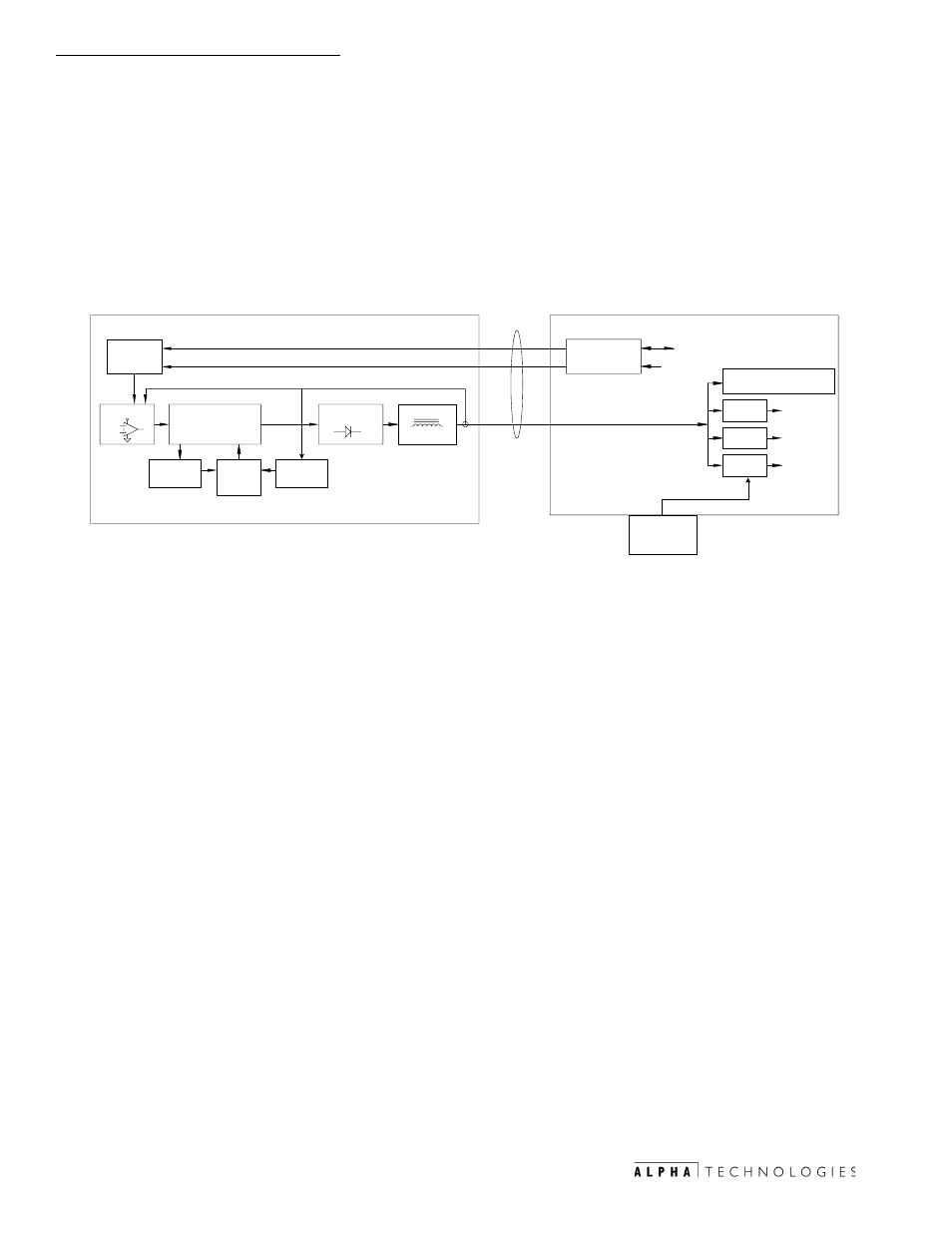
1. System Overview
16
031-132-B0-001 Rev. A
TM
©2000
The DC output of the APU connects directly to the inverter batteries to
recharge them when line power is lost and maintain an indefinite DC supply to
power supply inverter systems.
The 5kW version of the CE3X-2 AlphaGen system is ideally suited to provide
unlimited standby operation of approximately 100 hours (based upon fuel
capacity and oil capacity) to power systems utilizing 2 XM2 2000 Watt (or 3
XM2 1350 Watt) power supplies. The 14hp-rated single-cylinder overhead valve
(OHV) engine used in this application drives a direct-connect, variable-speed, 3-
phase permanent magnet generator (PMG) to produce a high-frequency AC
power. A 3-phase full-wave rectifier in the control system rectifies the output to
produce low-ripple DC power. The DC in-line fuse provides protection for
downstream devices in the event of overload or accidental short circuit.
8@YÃTr vrÃ6QVÃ@py r
8vphv
68ÃGvrÃTrr
98ÃTrrÃ7r rqÃ$xX
6yuh
@8H
8 y
6yuhBr
@tvr
Brr h
@tvr
8uh tr
8uh tr
!W
Dtvv
7hr
Srpvsvr
Dqp
Avyr
Dr shpr
8hiyr
6yuhÃTrÃ@py r
6yuh
Dr shpr
8
68ÃGvr
98
7
"%Г#'Г(%ГW98
7hr ÃQhpx
VQT
VQT
I
68Г
68Г
68Г
68ГGvr
Vvyv
Tr vpr
@ hpr
ÃUurÃsvyr ГvГ
rqÃvÃhyy
hyvphv
1.3
APU Overview
Alphas Auxiliary Power Unit (APU) provides a second source of power from
which the power supply systems can draw, in the event that the utility power
supplied to the system is lost or unacceptable (i.e., low or high voltage, noisy,
unstable, etc.). It consists of a gas driven (natural or propane vapor) engine/
alternator (DC).
Fig. 1-5 System Block Diagram