7 ecm alarm overview, System overview – Alpha Technologies AlphaGen 5.0kW Auxiliary Power Unit User Manual
Page 24
1. System Overview
24
031-132-B0-001 Rev. A
TM
©2000
1.7
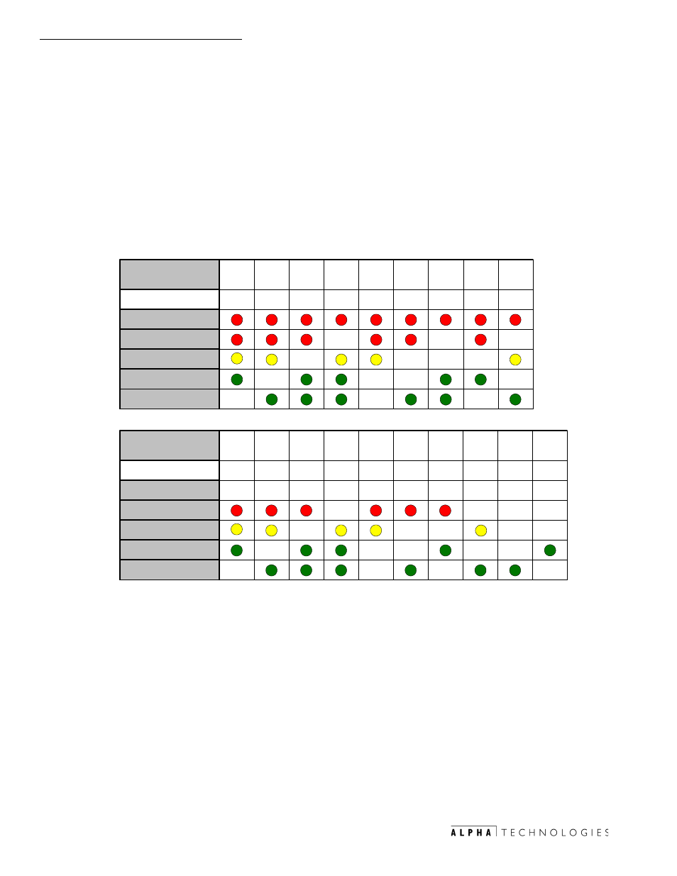
ECM Alarm Overview
Alarms are indicated in three ways: ECM LEDs, RS-485 communications
and alarm contact closures on ECM transponder interface. Alarm indication on
the ECM LEDs is obtained by pressing the service reset button momentarily and
noting the combination of illuminated LEDs. Pressing the service reset switch
again will reveal the next alarm in the list. When the alarm list has been
exhausted, all LEDs will flash several times and then return to their normal
functions. Placing the RAS switch to the STOP position for three (3)
seconds, then switching back to AUTO will clear any latched alarms and
start the generator if the cause of the alarm has been corrected. The
following table shows the LED patterns and the alarms they represent.
1. Low Oil Pressure (LO)*
2. Engine Over-Temp (OT)
3. Engine Over-Speed (OS)*
4. Engine Over-Crank (OC)*
5. Alternator Over-Volt (OV)*
6. Gas Hazard (GH)*
7. Water Intrusion (WI)
8. Pad Shear (PS)*
9. Low Fuel Pressure (LP)***
10.
Control Fail (CF)***
11.
Alternator OFF (AO)
12.
Self-Test Fail (TF)*
13.
Low Ignition Battery (IB)
14.
Auto-mode Disabled (AD)
15.
Tamper (TP)
16.
DC Bus fault (DC)
17.
Engine Disable (ED)
18.
Line Failure (LF)**
19.
Service Required (SR)**
Legend:
*
=
Latching Alarm
**
=
Notifications
***
=
Alarm latches after 5 activations
(LEDs as displayed on the ECM)
Hhw Ã6yh
6ii rvhv
Hhw
Hv
Ivs
8
Tr
!
"
#
$
%
&
'
(
GP
PU
PT
P8
BC
XD
QT
GQ
PW
Hhw Ã6yh
6ii rvhv
Hhw
Hv
Ivs
8
Tr
!
"
#
$
%
&
'
8A
6P
UA
D7
UQ
98
@9
GA
69
(
TS
Table 1-2 Major, Minor Alarm Indications, and Notifications