Interconnection, Pin description, 3 connectors, continued – Alpha Technologies AlphaGen 5.0kW Auxiliary Power Unit User Manual
Page 75
4. Interconnection
75
031-132-B0-001 Rev. A
TM
©2000
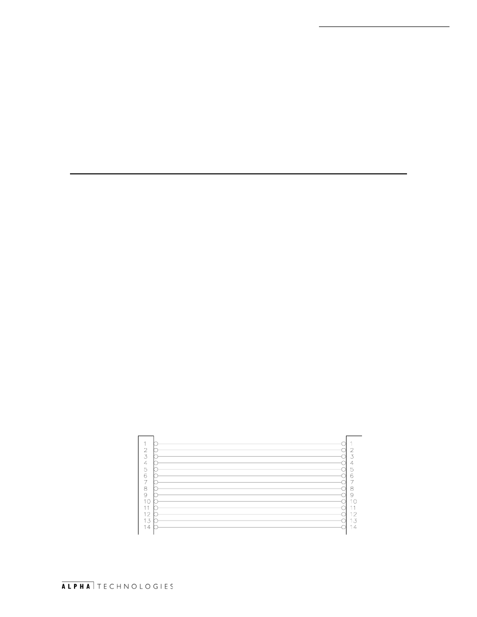
4.3.9 ECM-PWR GRI Enclosure Sensor Interface Ribbon Cable
The connector is a 14 pin 0.100 spaced, 150V rated ribbon cable with
polarized cable connectors that prevent incorrect connections in the field.
Designations for the connector mounted on the PCBA shall be identified by silk
screen J1 and marked with the #1 pin of the PCB receptacle for polarization.
See Fig. 4-9 for location.
Pin
Description
1
Low Oil Pressure*
2
Over-Temp*
3
Over-Speed*
4
Over-Crank*
5
Engine Run*
6
Over Voltage Shutdown*
7
Alternator Output Active (ON)* (Developed by Charger Circuit)
8
Switch Not In Auto* (Auto-Off-Manual switch control switch)
9
Low Ignition Battery*
10
Logic Common - all alarms listed above
11
Control RTY* (Relay Transfer Switch low = Generator AC power) (Referenced
to pin 13)
12
Start* and Engine Run Enable* (See below) (Also remote test from external
test routine)
13
Start/Stop Power Common
14
Stop* (To Stop APU after test is complete)
Note: Active low determined by (*) symbol.
Note: The Pin #12 serves two functions:
-Collocated operation with ACU, START* command causes the engine
to latch on and continue to run when START* is released.
-Remote operation with ECM, ENGINE RUN ENABLE* (Pin 12)
command enables the engine to run as long as the signal is held
active LOW, and shuts down when the ENGINE RUN ENABLE* is
released.
/2:
Г
2,/
29(5
Г
7(03
29(5
Г
63(('
29(5
Г
&5$1.
(1*,1(
Г
581
29(5
Г
92/7
Г
6+87'2:1
$/7
Г
287387
Г
21
6:,7&+
Г
127
Г
,1
Г
$872
/2:
Г
,*1,7,21
Г
%$77(5<
/2*,&
Ã
&20021
ГГ
$/$506
&21752/
Ã
57<
67$57
(1$%/(
3:5
Ã
&200
Г
)25
Г
67$57
6723
6723
Q E
Q E
72
Ã
(
&
0
72
Ã
3
:
5
*
5
,
(1*,1(
4.3
Connectors, continued
Fig.4-10 ECM-PWR GRI Enclosure Sensor Interface Ribbon Cable