12 ecm - enclosure alarm interface, Fig. 4-13 enclosure alarm interface, Interconnection – Alpha Technologies AlphaGen 5.0kW Auxiliary Power Unit User Manual
Page 78: 3 connectors, continued, Pin description function
4. Interconnection
78
031-132-B0-001 Rev. A
TM
©2000
4.3
Connectors, continued
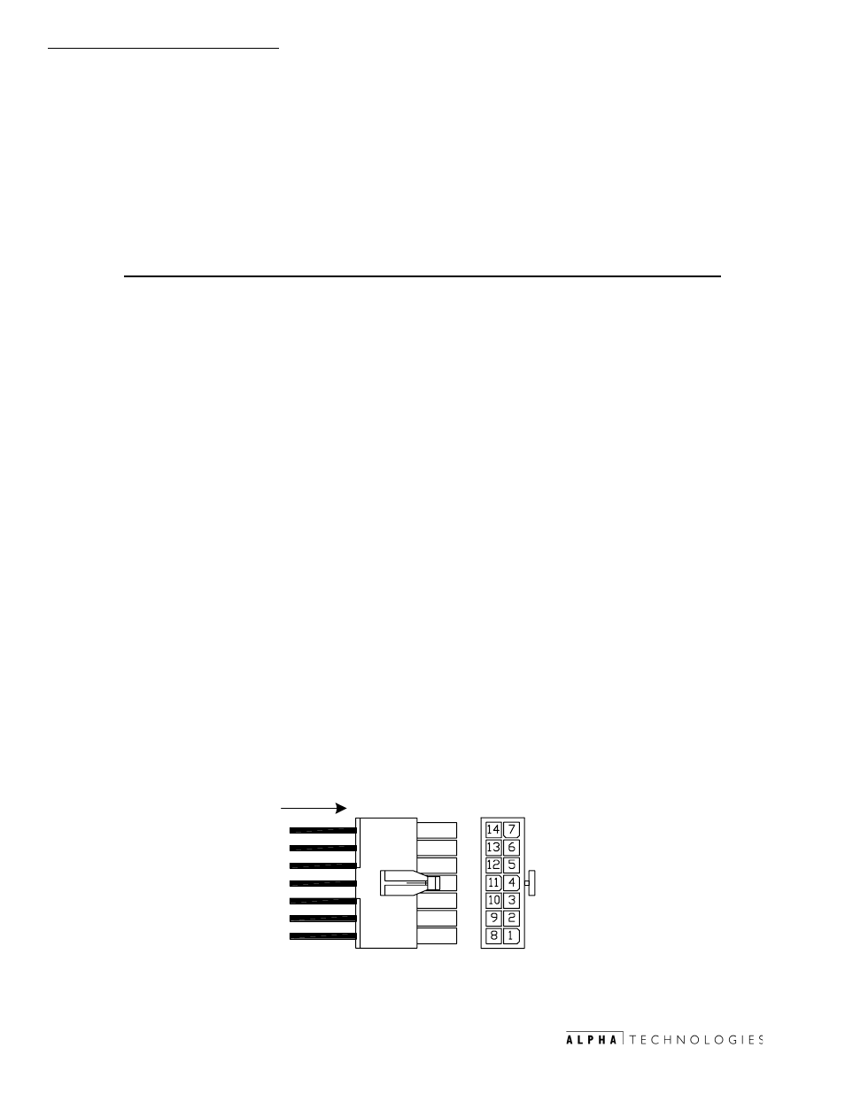
The Alarm Interface Connector (J10) connected to the Power PCBA. The
interface control is a 14-pin (2x7 row) Universal Mini Mate-N-Lok style male
connector. See Fig. 4-9, item 10 for location.
Pin
Description
Function
1
Water Intrusion Sensor
Contact OPEN (HIGH signal) denotes Water
Intrusion
2
Water Intrusion common
Return signal path for sensor
3
Pad Shear Sensor
Contact CLOSED (LOW signal) denotes Pad Shear
4
Pad Shear Common
Return signal path for sensor
5
Low Fuel Pressure Sensor
Contact CLOSED (LOW signal) denotes Low Fuel
Pressure (LPV Versions only)
6
Low Fuel Pressure Common
Return signal path for sensor
7
Gas Hazard Sensor Switch
Active OPEN signal denotes Gas Hazard
(Logic HIGH)
8
Gas Hazard Power/Alarm
(Common)
Return signal path for sensor
9
Gas Hazard Logic Power
(+12VDC Fused)
Logic Power for Logic PCB & sensor
10 Door Open Sensor
Contact CLOSED (LOW signal) denotes Door is
OPEN
11 Door Open Common
Return signal path for sensor
12 No Connection
13 Cabinet Fan +12V Fused
+12VDC supplied to Fan non-switched
14 Cabinet Fan Common
Return path for Fan
5($5 9,(:
:,5( 6,'(
-
5($5
9,(:
4.3.12 ECM - Enclosure Alarm Interface
Fig.4-13 Enclosure Alarm Interface