11 analog and logic power interface ribbon cable, Fig. 4-12 analog/logic power interface connection, Interconnection – Alpha Technologies AlphaGen 5.0kW Auxiliary Power Unit User Manual
Page 77
4. Interconnection
77
031-132-B0-001 Rev. A
TM
©2000
4.3
Connectors, continued
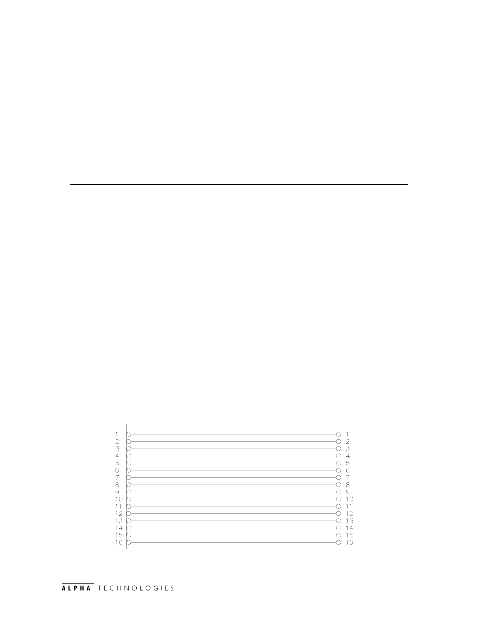
4.3.11 Analog and Logic Power Interface Ribbon Cable
Pin
Description
Function
1
Ign +12VDC RAW DC
(Fused @1Amp Slow Blow Ignition Battery)
2
Ign +12VDC RAW DC
(Fused @1Amp Slow Blow Ignition Battery)
3
Ign 12v Common Return
(For 12V RAW)
4
Ign 12v Common Return
(For 12V RAW)
5
Logic Common Return
(For digital and micro power)
6
Logic Common Return
(For digital and micro power)
7
Analog Common Return
(For AC & DC Sense circuits)
8
Analog Common Return
(For AC & DC Sense circuits)
9
Scaled Inverter Bus Pos
(Inverter Battery Bus Pos) (125VDC=5.0VDC
scale)
10
Spare
11
Scaled AC Line Input L1
(Line AC Output 16vac)
12
Scaled AC Line Input L2
(Line AC Output 16vac)
13
Scaled AC Gen Output L1
(Gen AC Output 16vac)
14
Scaled AC Gen Output L2
(Gen AC Output 16vac)
15
Out CT POS
(Gen AC Output Current Transformer)
16
Out CT NEG
(Gen AC Output Current Transformer)
This connector is a 16 pin 0.100 spaced, 150V rated ribbon cable with
polarized cable connectors that prevent incorrect connections in the field.
Designations for the connector mounted on the PCBA shall be identified by silk
screen J3 and marked with the #1 pin of the PCB receptacle for polarization.
See Fig. 4-9 for location.
!ÃW98ÃS6XÃDBIÃ76UUÃQPX@S
8PHHPIÃS@UVSIÃÃÃÃ !ÃWÃS6X
!ÃW98ÃS6XÃDBIÃ76UUÃQPX@S
8PHHPIÃS@UVSIÃÃÃÃ !ÃWÃS6X
GPBD8Ã8PHHPIÃS@UVSI
GPBD8Ã8PHHPIÃS@UVSI
6I6GPBÃ8PHHPIÃS@UVSI
6I6GPBÃ8PHHPIÃS@UVSI
T86G@9ÃDIW@SU@SÃ76UU@S`ÃQPT
TQ6S@
T86G@9Ã68ÃDIQVUÃWPGU6B@ÃG
T86G@9Ã68ÃDIQVUÃWPGU6B@ÃG!
T86G@9Ã68ÃB@IT@UÃWPGU6B@ÃG
T86G@9Ã68ÃB@IT@UÃWPGU6B@ÃG!
PVUÃ8UÃQPT
PVUÃ8UÃI@B
UP
Ã@
8
H
UP
ÃQ
X
S
B
S
D
Q"E"
Q"E"
$1$/2*
Fig.4-12 Analog/Logic Power Interface connection