Fig. 2-2, Generator set master switch, Fig. 2-3 – Alpha Technologies AlphaGen 5.0kW Auxiliary Power Unit User Manual
Page 30: Location of ecm run/auto/stop switch, Fig. 2-2 generator set master switch, Turn-up and test, 3 starting a local apu test, continued, 2 initial operation, continued
2. Turn-Up and Test
30
031-132-B0-001 Rev. A
TM
©2000
2.2.3 Starting a Local APU Test, continued
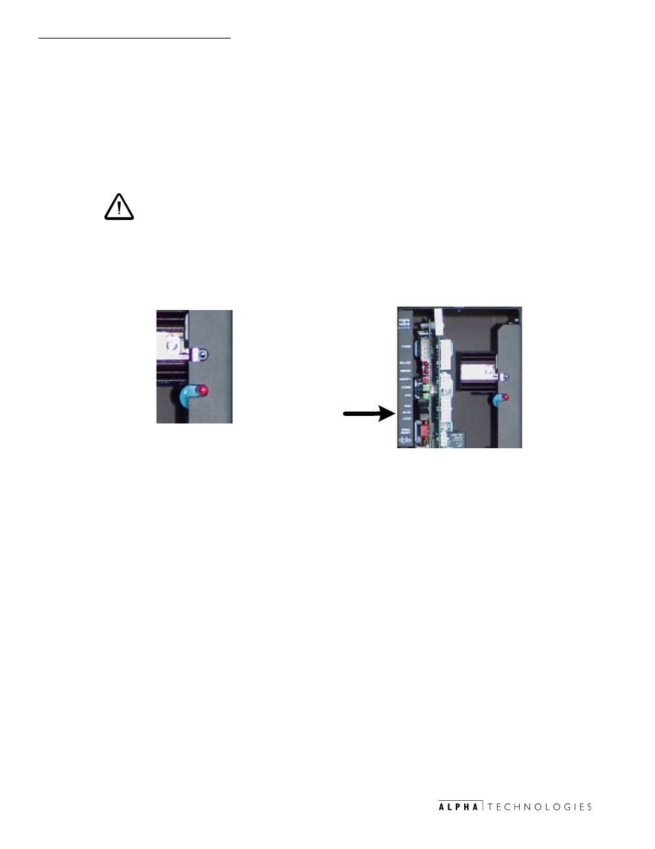
2. Place generator set master switch to the middle (ECM) position.
CAUTION:
The Generator Control Board master switch will override
the Run/Auto/Stop (RAS) switch on the ECM. This
switch is normally left in the center, or "ECM" position.
(On older 5kW generators, the center position may be
marked 'Auto' or be blank.)
STOP
E
C
M
START
STOP
E
C
M
START
2.2
Initial Operation, continued
3.
Set RAS switch to STOP
4.
Verify Ignition Battery & AC Line Sense connection to ECM.
5.
Verify all alarms on ECM are OFF except Tamper Alarm & Auto
Mode Disabled.
6.
Remove gas port plug from input side of demand regulator, install
brass manometer port connection fitting and connect manometer to
fitting (Refer to fig. 3-1, and Section 3-17 for further details).
7.
Move RAS switch from STOP to AUTO.
8.
Verify the engine starts within 3 salvo cycles per Table 1-1, Normal
Mode Crank Cycle.
9.
If engine fails to start within 3 salvo cycle and Engine Over Crank
isactivated, the gas line needs to be purged by removing air filter
and placing hand over the carbureator throat to choke while
cranking engine until engine starts.
10. Verify 11 of water column pressure is present at the input of the
demand regulator.
Fig.2-2
Generator set master switch
Fig. 2-3
Location of ECM Run/Auto/Stop switch