Fig. 4-8 alarm control interface connector, Fig. 4-8, Alarm control interface connector – Alpha Technologies AlphaGen 5.0kW Auxiliary Power Unit User Manual
Page 73: Interconnection
4. Interconnection
73
031-132-B0-001 Rev. A
TM
©2000
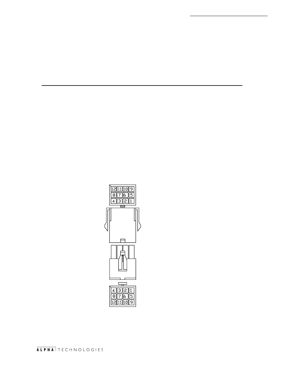
Pin Description
Function
1
+12V Ignition Battery
Ignition battery Fused 12V from APU.
2
Neg Ignition Battery
Ignition Battery Negative from APU.
3
Low Oil Pressure
Active LOW signal denotes Low Oil Pressure.
4
Over-Temp
Active LOW signal indicates Over Temp.
5
Start Command
Active LOW from ECM activates the APU START
relay.
6
Common (Start /Stop) Common return between Start and Stop relays.
7
Stop Command
Active LOW from ECM activates the APU STOP relay.
8
Over-Speed
Active LOW signal denotes engine RPM was exceeded.
9
Over-Crank
Active LOW signal denotes Over Crank Limit is
reached.
10
Engine Run
Active LOW signal denotes the Engine is Running.
11
Not Used
12
Not Used
4.3.7 Alarm Control Interface to APU Interface Connector (APU-I/O)
The interface control is a 12 pin (3x4 row) Mini Mate-NLok style connector. See
Fig. 4-1 for location.
7R
(&0 -
$38
,2
5HDU YLHZ
ZLUH VLGH
$38 ,2
,QWHUIDFH
&RQQHFWRU
5HDU YLHZ
ZLUH VLGH
)URP
$38 3&%
4.3
Connectors, continued
Fig. 4-8 Alarm Control Interface Connector