10 ecm and pwr-gri interface ribbon cable, Fig. 4-11 ecm and pwr-gri interface ribbon cable, Interconnection – Alpha Technologies AlphaGen 5.0kW Auxiliary Power Unit User Manual
Page 76: 3 connectors, continued pin description function
4. Interconnection
76
031-132-B0-001 Rev. A
TM
©2000
4.3
Connectors, continued
Pin
Description
Function
1
Gas Hazard*
2
Pad Shear*
3
Water Intrusion*
4
Low Gas Pressure*
5
Door Open*
(Does not disable APU RUN operation, alarms only)
6
FE Gas Hazard*
(External Fuel Enclosure)
7
FE Pad Shear*
(External Fuel Enclosure)
8
FE Low Gas Pres*
(External Fuel Enclosure)
9
FE Door Open*
(External Fuel Enclosure)
10
Logic Common
Logic Common - Enclosure sensors
Note: Active low determined by (*) symbol.
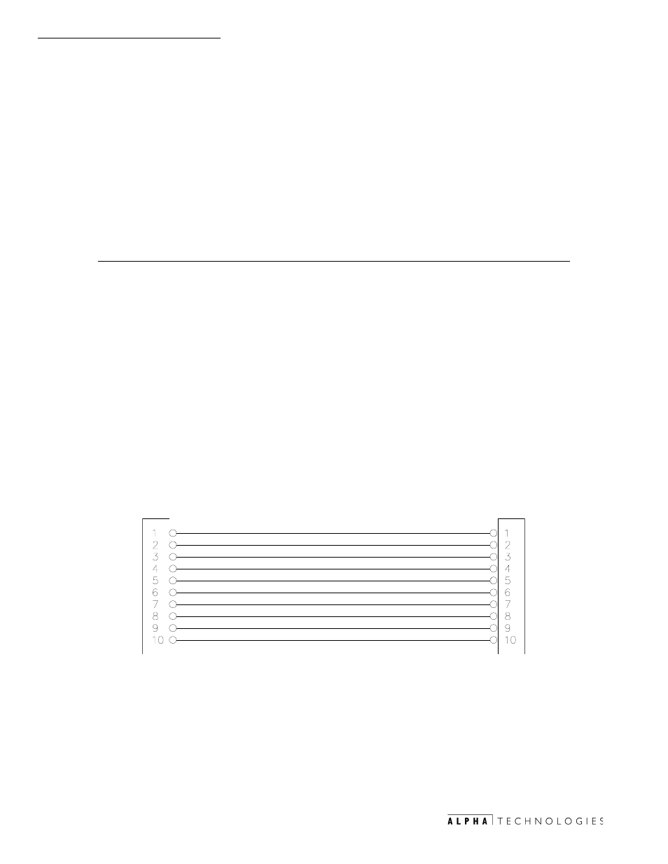
This connector is a 10 pin 0.100 spaced, 150V rated ribbon cable with
polarized cable connectors that prevent incorrect connections in the field.
Designations for the connector mounted on the PCBA shall be identified by silk
screen J2 and marked with the #1 pin of the PCB receptacle for polarization.
See Fig. 4-9 for location.
4.3.10 ECM and PWR-GRI Interface Ribbon Cable
*$6 +$=$5'
3$' 6+($5
:$7(5 ,17586,21
/2: *$6 35(6685(
'225 23(1
)( *$6 +$=$5'
)( 3$' 6+($5
)( /2: *$6 35(6
)( '225 23(1
/2*,& &20021
(1&/2685(
72
(
&
0
72
3
:
5
*
5
,
3-
3-
(1&/2685(
Fig.4-11 ECM and PWR-GRI Interface Ribbon Cable