3 connectors, 1 gas hazard alarm interface, 2 low fuel pressure interface connector – Alpha Technologies AlphaGen 5.0kW Auxiliary Power Unit User Manual
Page 67: Fig. 4-2 gas hazard detector interface, Gas hazard alarm interface, Fig. 4-2, Gas hazard detector interface, Interconnection
4. Interconnection
67
031-132-B0-001 Rev. A
TM
©2000
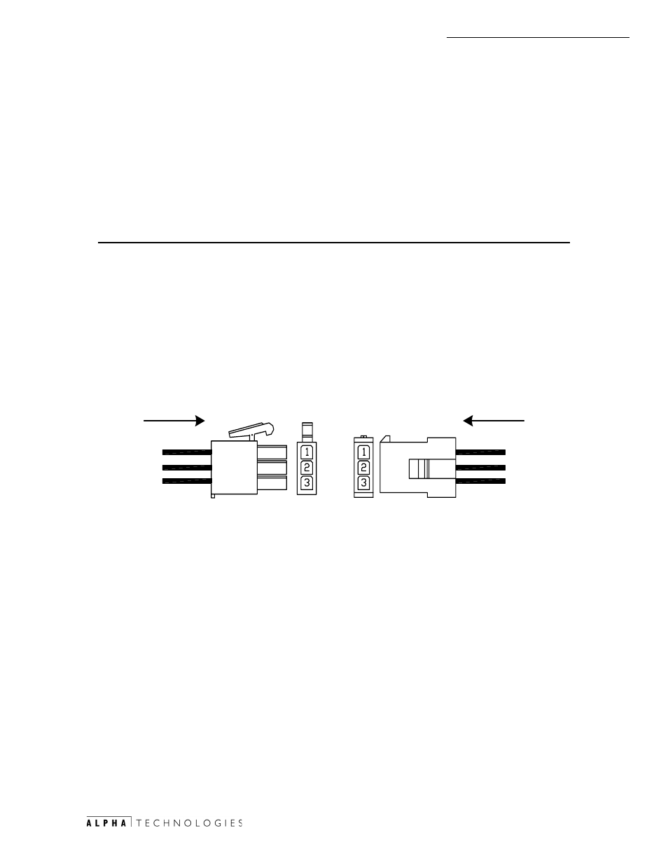
The Gas Hazard Detector Interface Connector is connected between the wire
harness and detector unit as shown. The interface control is a 3-pin (1x3 row)
Universal Mini Mate-N-Lok style male connector. See Fig. 4-1 for location.
Pin
Description
Function
1
Gas Hazard Sensor Switch
Active OPEN signal denotes Gas
Hazard (Logic HIGH)
2
Gas Hazard Power/Alarm Common
Return signal path for sensor
3
Gas Hazard Logic Power +12VDC Fused
Logic Power for Logic PCB & sensor
*+'
5($5
9,(:
5($5
9,(:
72
(&0
)520
6(1625
5HDU YLHZ ZLUH VLGH
4.3.1 Gas Hazard Alarm Interface
4.3
Connectors
Fig. 4-2 Gas Hazard Detector Interface
See also other documents in the category Alpha Technologies Equipment:
- AlphaCell GelCell Series (32 pages)
- FXM 650, 1100, 2000 UPS (96 pages)
- Cordex 48-1.2kW (68 pages)
- Radium MiniBay (57 pages)
- Fiber Backhaul Enclosure (FBE) (19 pages)
- FBE2322 Enclosure System (38 pages)
- FlexNet PMR, GMR Series (49 pages)
- Te25xh (38 pages)
- FlexNet MPS48-12M - Technical Manual (33 pages)
- FlexNet MPS48-12M - Quick Start Guide (2 pages)
- FlexNet ELPM 300-48D (25 pages)
- FlexNet FMPS (40 pages)
- FlexPoint AX Series (34 pages)
- FlexPoint FPR1207-F - Technical Manual (18 pages)
- FlexPoint FPR1207-F - Quick Start Guide (2 pages)
- AlphaGen PN-6x-T 7.5kW 48VDC - Installation and Operation Manual (79 pages)
- AlphaGen CE-3x2 5K-T 48Vdc (95 pages)
- AlphaGen PN-6x-T 7.5kW 48Vdc (95 pages)
- AlphaGen 3.5_5.0kW Kohler COM5 (80 pages)
- Security Bar Field For UPE-3, UPE-6, UPE-M3, UPE-M6, PN Series and CE Series (2 pages)
- AMPS80 HP (116 pages)
- 255A Bypass Switch (24 pages)
- AMP24 HP (108 pages)
- FXM350_Micro350 UPS (112 pages)
- CFR 600, CFR 600XT, CFR 1000 (70 pages)
- BPS Series Bypass Switch (36 pages)
- CFR Intelligent Interface Device (54 pages)
- CFR Redundant Control Unit (23 pages)
- CFR 5000, CFR 5000RM (88 pages)
- CFR 3000, CFR 3000RM (86 pages)
- CFR 1500, CFR 1500RM (83 pages)
- CFR 1500, CFR 2000, CFR 2500, CFR 3000 (76 pages)
- Continuity: 1000_2000_3000 (48 pages)
- Continuity Battery Pack (20 pages)
- Continuity: 6K_10K (52 pages)
- Micro, Micro XL, Micro XL3 UPS (99 pages)
- Micro Secure UPS (80 pages)
- Te17 (32 pages)
- Te45 (68 pages)
- Te41, 48V (76 pages)
- Te41, 24V (72 pages)
- Te43 (60 pages)
- AlphaGuard AG-CMT Installation (2 pages)
- AlphaGuard AG-CMT-3SC_4SC-P (2 pages)
- Digital Midtron DM-3200 AT (2 pages)