2 ecm interface topology and connectors, Fig. 4-1 ecm/apu interconnection, Fig. 4-1 – Alpha Technologies AlphaGen 5.0kW Auxiliary Power Unit User Manual
Page 66: Ecm/apu interconnection, Interconnection, 8urrp 8 hv, Q ãxhuvt i, Hp9@g cd8
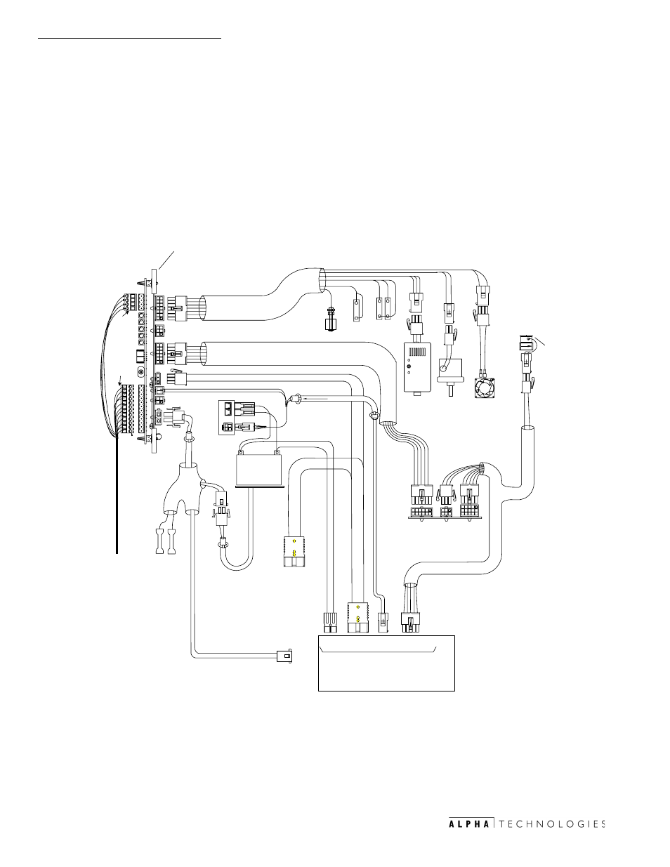
4. Interconnection
66
031-132-B0-001 Rev. A
TM
©2000
4.2
ECM Interface Topology and Connectors
The ECM PWR- GRI PCBA provides the interface between cabinet sensors,
APU control, and power conditioning to the ECM. The interface also supplies all
the necessary signals, alarms, logic power, and analog voltages required for
telemetry to the cable head end, central office, or network manager, and allows
the Alpha Systems control module to start and stop the Engine alternator as
part of network controlled periodic tests and exercises.
3
2
6
98ÃPVU
@IBDI@Ã6GU@SI6UPS
8PHQ6SUH@IU
3:5*5,
QDIÃ
6QVÃ8PIUSPG
Q69
X6U@S
9PPS
TC@6S
6G6SH
1
(
*
GDI@
T@IT@
DIU@SA68@
DIU@SA68@
B6T
T@ITPS
,17586,21
PQ@I
DIWÃ76UU@S`ÃT@IT@
1
(
8
7
9
E
E%
BC9
QGVB
8urrp
8 hv
'#!
Q ÃXhuvt
I`
6G6SH
HP9@G
CD8
B6TÃ9@U@8UPS
S@T@U
S@69`
GPXÃAV@G
QS@TTVS@
GAQ
QGVB
A6I
3
2
6
1
(
*
'
&
1
'
&
3
6QV
8PIUSPGÃQ87
T@@Ã6GQC6Ã$ÃH6IV6G
3
2
6
1
(
*
DBI
76UU
GDI@
T@IT@
-
%
/.
5
(
'
98ÃQPX@S
S@9
76UU@S`
Ã
C@6U@S
PQUDPI
ГГ !
W
98
Ã
PVUQVU
Ã
7VT
&+$5*(5
Ã
&21752/
@8H
QDIÃ
TPG@IPD9
B6T
BT8
QGVB
E#
E'
7GP8FÃC@6U@S
PQUDPI
$Ãv
HHG
%Ãv
HHG
!Ãv
6HQ
$Ãv
HHG
!Ãv
HHG
DBIDUDPI
76UU@S`
6G6SH
DIU@SA68@
PVUQVU
Fig. 4-1 ECM/APU Interconnection