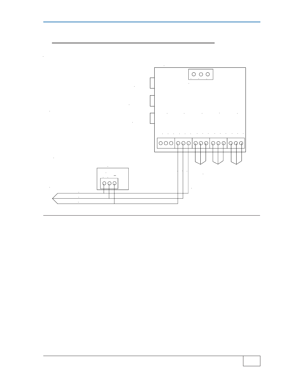
Stand alone ts-tpi, Hos t por t po r t 1 po r t 2 po rt 3 po r t 4, Figure 2-6 – Franklin Fueling Systems TS-TPI User Manual
Page 13
Installation and Wiring
Page
2-7
2
TS-TPI Installation and Wiring Guide
Stand AloneTS-TPI with TPCs
●
Communication between TS-TPI and TPCs. Use this application for remote
controller fault indication and controller fault reset.
●
Stand Alone TS-TPI requires separate 120 - 240 vac, 50/60 hz, power
●
TS-TPI reset switch will reset the TS-TPI in the event of a communication conflict.
●
The TPC fault reset will reset a pump controller that is in a fault conditon. It will
only reset controllers that are indicating a fault alarm. If none of the controllers are
in alarm no reset will take place.
●
Alarm Silence button will silence the audible alarm but not clear the fault.
●
Connect TPCs so all Stand alone TPCs are on the same port and Master/Slave
configured units are on their own port. Address TPCs so controllers on same port
have unique addresses.
STAND ALONE TS-TPI
T
X
D
4
85-
GN
D
R
X
D
485+
T
X
D
485
-
GN
D
R
X
D
485+
T
X
D
4
85-
GN
D
R
X
D
485+
T
X
D
4
85-
GN
D
R
X
D
485+
T
X
D
4
85-
GN
D
R
X
D
485+
HOS
T
POR
T
PO
R
T
1
PO
R
T
2
PO
RT 3
PO
R
T
4
ADDITIONAL TPC
GROUPS
RE
D
WH
IT
E
BL
AC
K
CABLE-BELDEN CONDUCTOR
#9365-18AWG OR EQUIVALENT
+ G
RS485
TPC
CONTROLLERS MAY INCLUDE THE
MagVFC, STP-SCI, STP-SCIII, IST-VFC
AND STP-SC
ADDITIONAL
TPC CONNECTIONS
RED
WHITE
BLACK
GND L2/N
L1
INPUT POWER
SPECIFICATIONS
Input power:
120 - 240 Vac 50/60 hz
Indoor installation only.
Operating temperature:
40 - 105° F (4 - 41° C)
TS-TPI
RESET
TPC FAULT
RESET
ALARM
SILENCE
Figure 2-6