Xylem System 5000 User Manual User Manual
Page 13
Hardware Overview
11
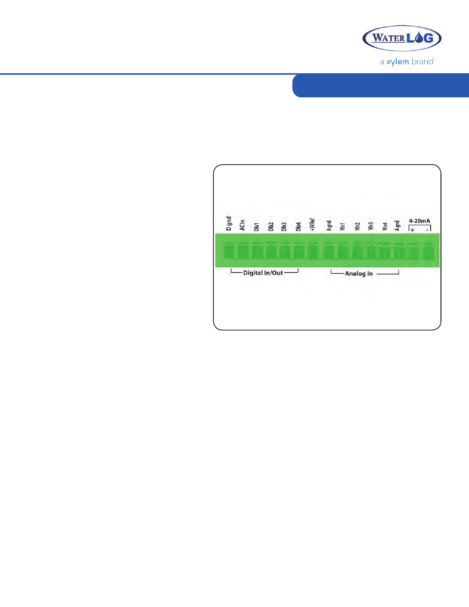
The lower right terminal strip is used for analog input functions. This includes four analog inputs, two
analog grounds, and one +5Vref excitation connection.
Analog Input Section
The AC Input is provided to connect sensors that have a low level AC output like wind speed
sensors. A wind speed sensor has at least two connections: Signal (ACIn) and Reference (Dgnd).
AC Input
The Digital I/O connections can be
configured independently as inputs or
outputs. In the input mode, the signal has
an internal pull up resistor of 47K Ohms.
This allows a switch closure to ground to
activate the input. It can also be driven
using normal logic levels. As an output,
a 100-Ohm protection resistor limits
the drive capability. The output will still
be about 4.0 volts with a 10.0mA or less
load. When a pair of digital I/O pins is
configured as inputs, they may be used as
a quadrature shaft encoder input.
Digital I/O
There are four analog input channels labeled Vin1 to Vin4. The standard input range for all channels
is 0 to 5 volts; however, because the Analog to Digital converter is highly accurate, it
can accurately measure low level ranges as well. Differential measurements can also be made on
channels Vin1 and Vin2 or on channels Vin3 and Vin4.
Analog Input Channels
There are two analog ground connection points. In order to preserve signal integrity, it is
important to use the analog grounds only for sensors connected to the analog section. The current
flowing through an analog sensor is relatively small and normally very stable. If a digital sensor
has its ground connection tied into the analog ground, the currents from the digital sensor will
flow through the analog circuitry causing voltage level shifts and noise based on digitalswitching.
There should be sufficient digital ground connection points for the digital sensors.Power grounds
should not be connected to analog grounds.
Analog Grounds