Hardware overview – Xylem System 5000 User Manual User Manual
Page 12
10
HARDWARE OVERVIEW
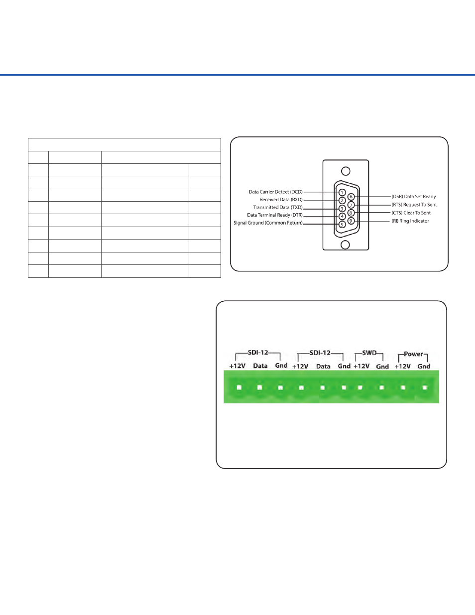
The SDI-12 Ports are provided to connect
SDI-12 compatible sensors. Standard SDI-
12 sensors have a minimum of three wires,
which are +12V, Data, and Gnd. There are
two SDI-12 ports, as shown above, for ease
of connecting multiple SDI-12 sensors.
SDI-12 Ports
The Switched +12 volt excitation is
provided to power sensors and, by default,
this port is always on. There are sensors
that only need to be powered when being
measured. To save on power consumption,
this port can be programmed to turn on
only during scans.
Switched +12 Volt Excitation
The Power connection is the main System 5000
™
power and ground. The power LED on the front
panel will blink every five seconds when sufficient power is connected.
Power Connection
Serial Port Pin-Out
PIN DIRECTION
NAME
1
Input
Data Carrier Detect
(DCD)
2
Input
Receive Data
(RD)
3
Output
Transmit Data
(TD)
4
Output
Data Terminal Ready
(DTR)
5
N/A
Ground
(GND)
6
Input
Data Set Ready
(DSR)
7
Output
Request To Send
(RTS)
8
Input
Clear To Send
(CTS)
9
Input
Ring Indicator
(RI)
The pin out for the RS-232 ports is shown below.