Install converters, Install battery voltage temp (vt)-probes, Figure 76 main screen - web – GE Industrial Solutions H5692448 Power Systems Infinity M1 (NE-M) User Manual
Page 54: Figure 76
NE-M
Installation Guide
H5692448
CC848815325 r06 May 2013
54
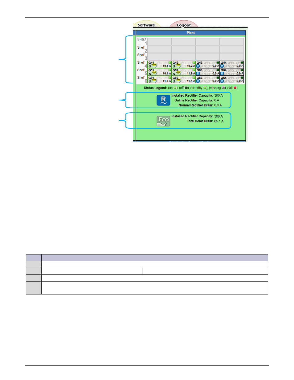
Figure 76 Main Screen - web
Install Converters
Repeat the above steps for converters; use converter-only slots first if provided. These are the lowest mounted
shelves and labeled “Converter Only”.
For more information on rectifiers and converters, see the Troubleshooting section.
Install Battery Voltage Temp (VT)-Probes
QS873A VT Probes can be used with or without mid-string voltage monitoring. Only one probe is required to allow
the battery slope thermal compensation function to be utilized.
Refer to the Galaxy Pulsar Plus Family Product Manual for installation instructions.
Install Aux Display (NE830A) Alarm Cable (Optional)
The optional NE830 Aux Display, when ordered separately, will require field installation. To do so, perform the
following steps:
Step
Action
Is the NE830A factory installed?
No – go to Step1.
Yes – go to Step4.
1
Connect and wire to field installed NE830A.
2
Install wiring per NEC and local rules for Class 3 circuits.
Note: Cable supplied with NE830A is suitable for Class 3 circuits.
AC Powered
Rectifier Capacity
DC Powered
Eco leaf symbols Indicate
DC Powered Rectifiers