Verify installation, Figure 57 bolt-in breakers – GE Industrial Solutions H5692448 Power Systems Infinity M1 (NE-M) User Manual
Page 38
NE-M
Installation Guide
H5692448
CC848815325 r06 May 2013
38
Bolt-In Breakers
Figure 57 Bolt-In Breakers
1
Assemble load bus bar to breaker using provided screws, nuts, and washers.
Torque nuts to 240 in-lb – 9/16” socket.
2
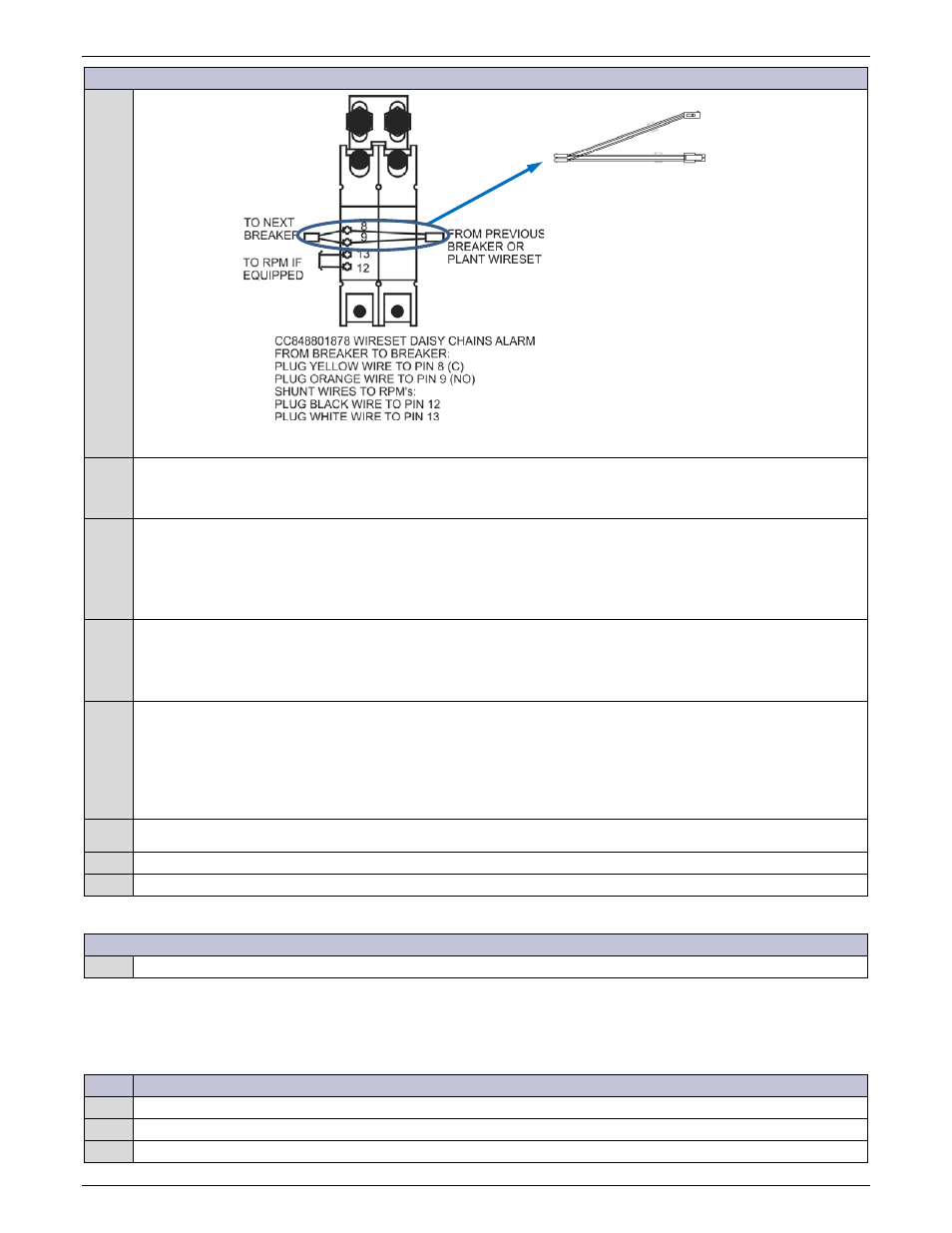
Install alarm wire set.
Alarm wire set daisy chains from Plant Wire Set through all bolt in breakers.
1. Connect wire set to breaker pins 8 & 9.
2. Connect wire set to plant wire set (if first bolt in breaker) or to previous breaker.
3
Install Bolt-in breakers into specified position using provided hardware.
3. Install standoffs - torque to 65 in-lb.
4. Secure load bus to standoffs with flat head screws - torque to 65 in-lb – 7/16” socket.
5. Secure breaker to load bus with hex screws and washers - torque to 240 in-lb – 9/16” socket.
4
Secure Load Cable connections with provided hardware (per cable):
(2) 3/8-16 nut
(2) 3/8-inch lock washer
(2) 3/8-inch flat washer
Torque to 240 in-lb - 9/16” socket.
5
Verify polarity (using a voltmeter) of the voltage between the Return bus and the distribution input bus.
6
Verify wiring polarity at the input of the load equipment.
Leave breaker switches in the OFF position until the load equipment is ready to be energized.
Re-secure Retainer Cover
1
Re-secure hinged retainer cover if removed.
Verify Installation
Perform the following verification checklist after installation of batteries and wiring:
Step
Action
1
Verify cabinet is properly grounded (using Digital Multimeter (DMM)).
2
Verify the AC equipment ground is properly connected.
3
Verify the correct ground cable gauge is used. Use the standard grounding principles for the office.
to Other Breakers
or Plant Wire Set
Shunt
to Pins
8 & 9