Connect controller wiring – pulsar plus, Figure 62 1-wire jumper - pulsar plus, Figure 63 controller connections – GE Industrial Solutions H5692448 Power Systems Infinity M1 (NE-M) User Manual
Page 42
NE-M
Installation Guide
H5692448
CC848815325 r06 May 2013
42
Step
Action – Pulsar Plus
5
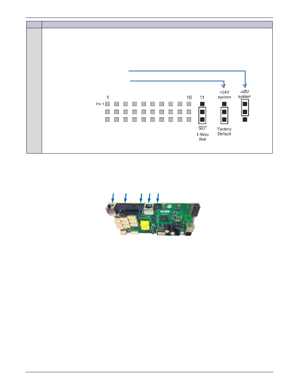
Configure the 1-Wire serial bus reference
The ES771 modules must be referenced to the most negative potential of the DC bus. This reference is
achieved by the proper setting of Jumper 11 next to the relay configuration jumpers. Following are the
appropriate settings for negative and positive power plants. The jumper is set in the factory for positive
systems unless the controller is shipped with an assembled system that has a pre-determined primary output
bus. It is suggested that an insulated tool be used to set the jumpers.
Figure 62 1-Wire Jumper - Pulsar Plus
Connect Controller Wiring – Pulsar Plus
All connections to the controller are made through appropriate cable assemblies. The controller has been designed
to separate outputs, inputs, communication, and plant specific items onto to individual connectors.
Figure 63 Controller Connections
Many systems are shipped with the appropriate controller connections wired by the factory. The following provides
a brief description of how and what to connect to the controller. Use only those sections that apply to the system
configuration.
+24V systems Jumper Position
-48V systems Jumper Position
J5
J4
J3 J2 J1