Figure 68 alarm connections millennium ii – GE Industrial Solutions H5692448 Power Systems Infinity M1 (NE-M) User Manual
Page 49
NE-M
Installation Guide
H5692448
CC848815325 r06 May 2013
49
Step
Action – Millennium II
3
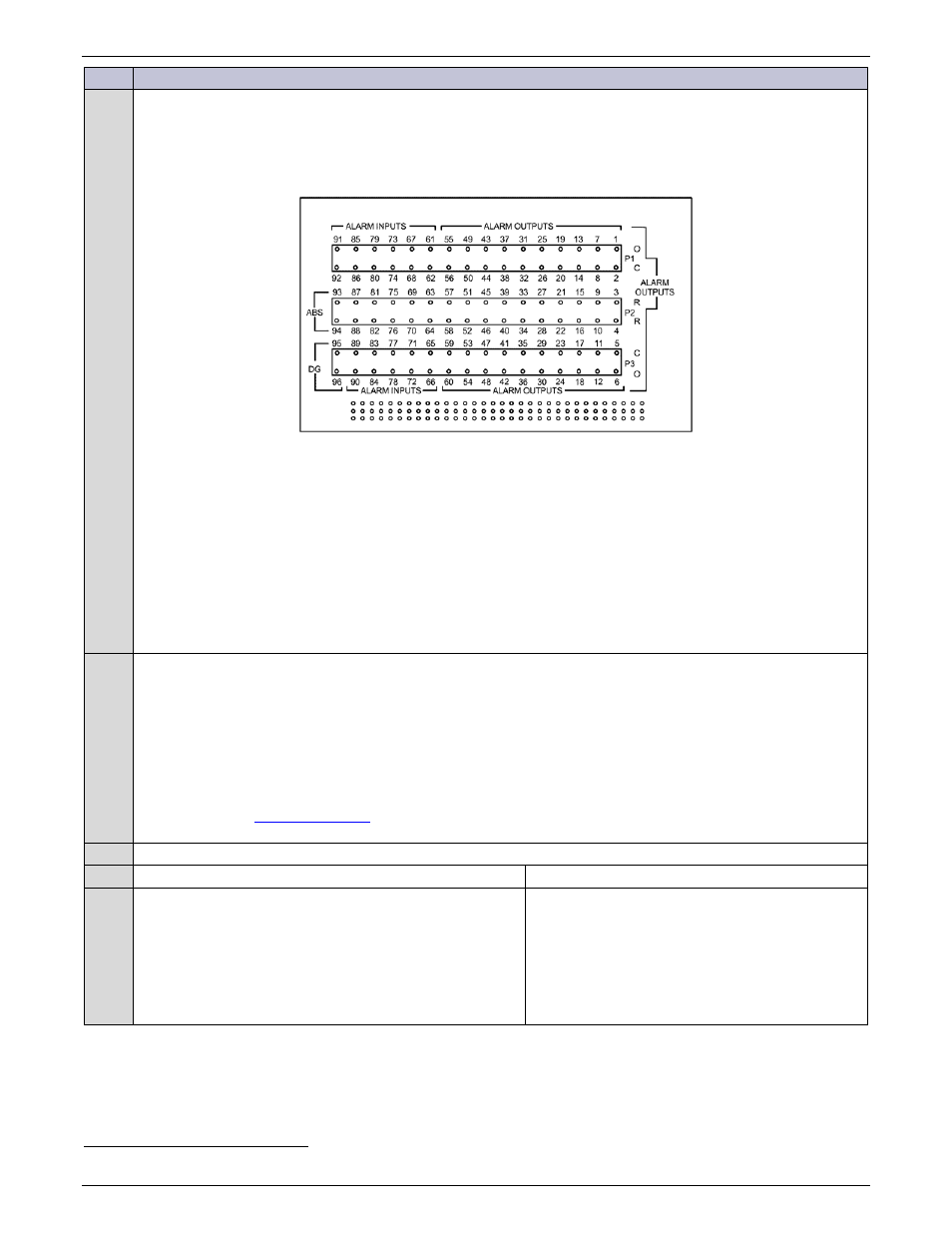
Alarm and Control Connections
Connect and wire alarm and control signals to the BSL card as specified in site engineering instructions.
Refer to Galaxy Millennium II Installation and User’s Guide alarm and control connection details.
Figure 68 Alarm Connections Millennium II
NOTE: Wire Wrap
Use 24 to 30 AWG wire.
Strip approximately 1 inch of insulation from wire.
Use a standard wire wrap tool to connect each wire to its terminal.
Punch Down Use 18 to 22AWG (if less than 18AWG, use multi-conductor cable for mechanical
integrity).
Secure wires to terminals using a punch down tool or
Phillips #1 or #2 screwdriver inserted into a punch down insulating cap
4
Network (LAN) Connection (Optional)
Connect to network.
The controller provides an Ethernet connection for a LAN and or Craft port connection. Connector P2 provides
a standard RJ45 shielded receptacle connection for a standard Cat-5 connection to the controller’s
10/100Base-T port. This port has two main modes of operation: Server mode, LAN mode (Static and DCHP
Client). In server mode the port can be used as a local Craft interface. In this mode, a local laptop can be
connected through J5 and its standard web browser used to directly access the controller by typing in
network addres
connection should never be made between the controller and LAN
while the controller is in Server mode.
Is the controller equipped with the Modem Option?
Yes – go to Step 6.
No – go to Step 7.
5
Telephone Line Connection (Optional).
Door-mount MODEM option provide their own RJ11
connection for the telephone line.
Use appropriate routing techniques to connect the
controller respective RJ11 to the telephone line.
Modem is mounted on door near the controller.
19
Punch down caps are furnished with the controller.