Install controller, Install pulsar plus, Figure 58 rectifier positions – GE Industrial Solutions H5692448 Power Systems Infinity M1 (NE-M) User Manual
Page 39
NE-M
Installation Guide
H5692448
CC848815325 r06 May 2013
39
Step
Action
4
Verify the AC voltage supplied matches the AC input voltage of the rectifiers.
5
Verify all cables are properly installed for the distribution and labeled as 48 V or 24 V.
6
Examine to assure no sharp corners are in contact with dressed wires.
Modify to correct any problems found.
7
Check for conductor clearance within the bay associated with high power.
8
Check that all breakers are OFF and all fuses not inserted.
9
Verify the battery contactors are open, if equipped.
Manually operate them to the open position, if necessary, by pushing the contacts apart.
10
Verify the polarity of all battery cables (using DMM).
11
Verify no shorts are present between frame ground and the AC service. Measure resistance from each AC
input line terminal block position to frame ground.
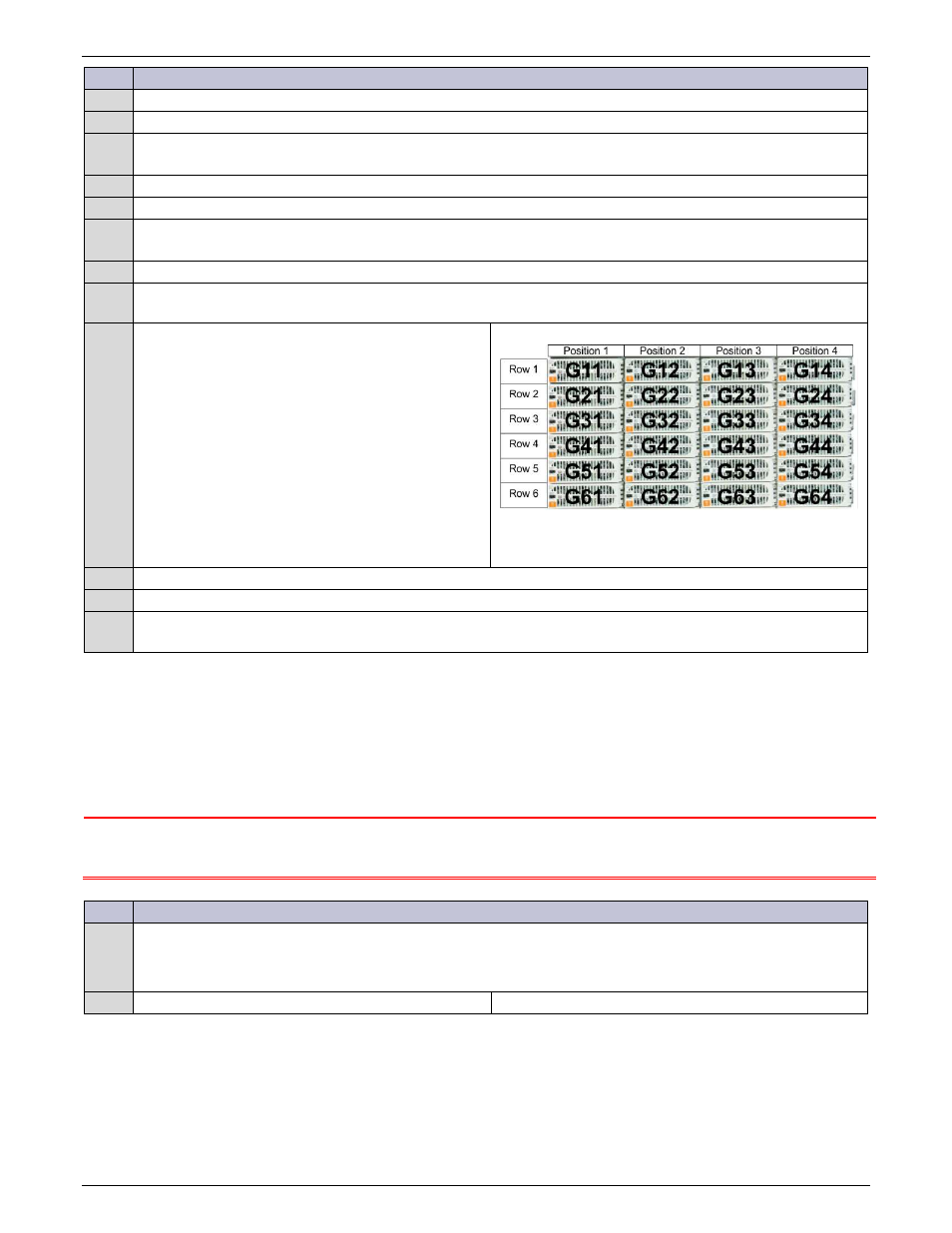
12
Verify shelves and rectifier positions are properly
identified. Label positions as necessary.
Example is for 5-shelf (row) system (front view).
Front View
Figure 58 Rectifier Positions
13
Verify battery negative cables are connected to the appropriate bus bar.
14
Verify battery positive cables are connected to the appropriate bus bar.
15
Visually verify cables the RS485 cables are properly installed and that shelf ID settings at the rear of the frame
are: [Shelf 1, Shelf 2, Shelf 3, etc.] from top to bottom.
Install Controller
Follow the procedures for the controller present in the system.
Install Pulsar Plus
Note: The controller is factory installed and connected to the NE-M equipment.
Connections to the controller made during installation are described here.
CAUTION: Equipment Damage
ESD NOTE: You must protect against ESD prior to configuring and installing the following circuit
cards.
Step
Action – Pulsar Plus
Configuring Individual Alarm Output Contact Type – “Close” on or “Open” on alarm
The factory default configuration for all alarm outputs is “Open On Alarm” on alarm.
Is this acceptable?
Yes – go to Step1.
No – go to Step4.