Connect input power, Figure 24 label input panel, Figure 25 label input panel cover – GE Industrial Solutions H5692448 Power Systems Infinity M1 (NE-M) User Manual
Page 23: Figure 26 input power terminal block positions
NE-M
Installation Guide
H5692448
CC848815325 r06 May 2013
23
Step
Action
8
Apply labels to the Input Panel chassis.
• Place “PV Wiring” label on the left (PV) side of partition.
• Place the “AC Wiring” label on the right (AC) side of
partition.
Figure 24 Label Input Panel
9
Replace the Input Panel cover and secure fasteners.
10
Apply 2 labels to Input Panel cover in any available space.
• Warning label
• Max Power-Point label
Figure 25 Label Input Panel Cover
Connect Input Power
WARNING: Shock Hazard
Disconnect all input branch circuits prior to making input connections to the system. When
connecting to any source, ensure compliance to all local and national wiring rules.
CAUTION: Equipment Damage
PV inputs must be current limited to 11A maximum.
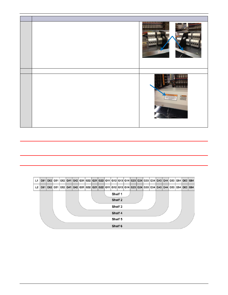
Terminal Block are arranged to allow addition of shelves (to the bottom) and terminal blocks (from the inside out).
Example shown is for 4-shelf system; up to 6 shelves are allowed.
Figure 26 Input Power Terminal Block Positions