Figure 10 power input panel, Figure 11 battery stand, Power input panel – GE Industrial Solutions H5692448 Power Systems Infinity M1 (NE-M) User Manual
Page 14: Battery options and monitoring features
NE-M
Installation Guide
H5692448
CC848815325 r06 May 2013
14
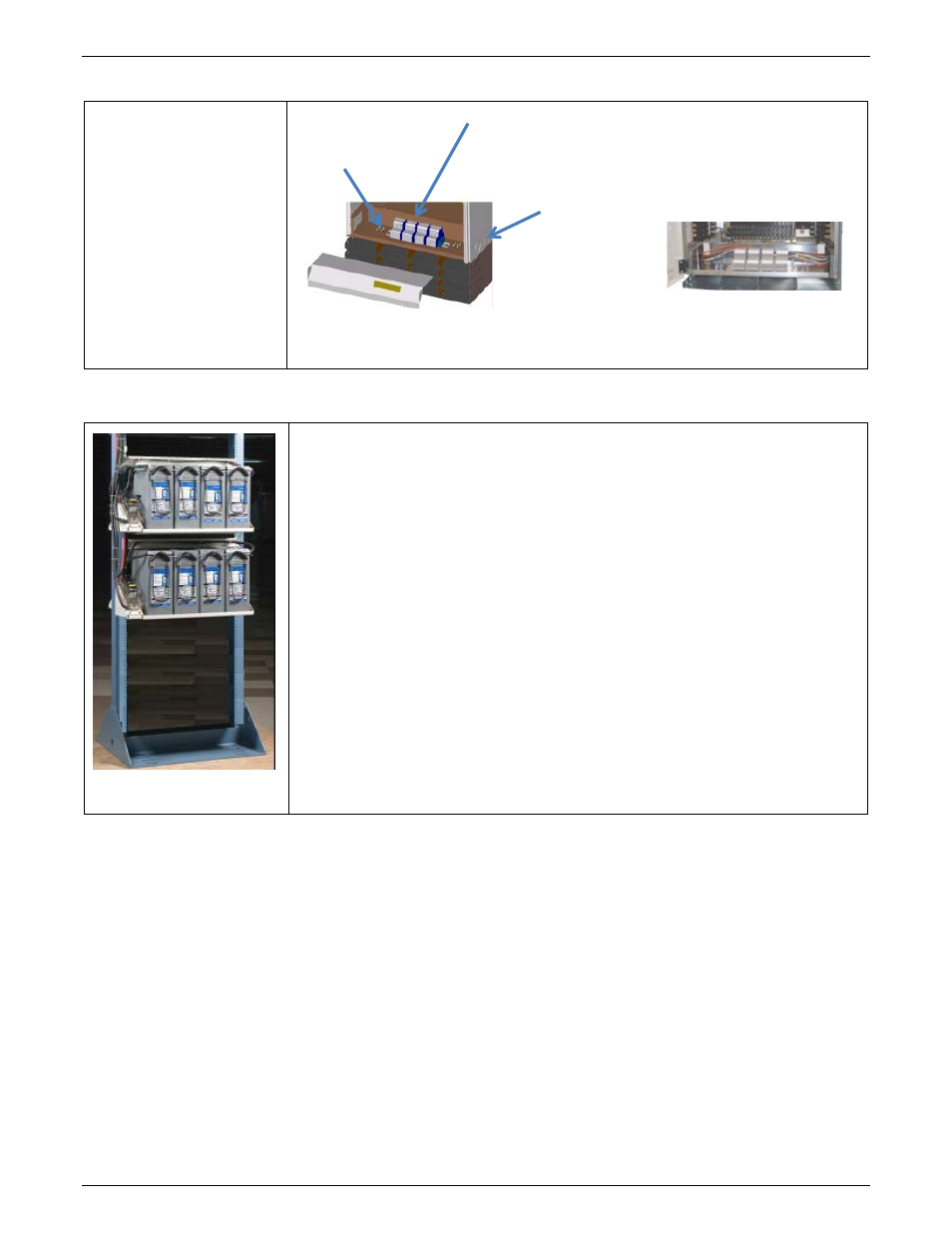
Power Input Panel
Power Input
Terminal blocks in a front
access panel at the bottom
of the distribution box.
Figure 10 Power Input Panel
Battery Options and Monitoring Features
Figure 11 Battery Stand
Battery Options
• Designed for operation with GE flooded, VRLA and Durathon™ Sodium batteries,
as well as other vendors’ batteries.
• Battery trays are available for 100Ahr to 170Ahr batteries with Anderson
PowerPole® connectors or circuit breaker disconnects.
• Half-height and third-height systems can be mounted on floor-mounted VRLA
strings or on GE Universal Battery Stands.
Battery Monitoring Features
• Open String (OS) Alarms
• Emergency Power Off (EPO) for disconnecting batteries from the system
• Temperature/voltage probes (up to 16) used in Battery Management options
• Slope Thermal Compensation – High and Low Temperature
• Battery High Temp Disconnect
• Mid-String Voltage Monitoring
• Battery Discharge Test
• Battery Shunt
• Low Voltage Battery Disconnect/Reconnect Contactor (LVDB)
with Emergency Power Off (EPO)
Knockouts
each side:
(2) 1” and
(2) 1-1/2”
Terminal Blocks Accept 24-
6 AWG wire.
Straps provided to
feed rectifier pairs.
Conduit Ground
¼-20 x 0.75” or
0.625” Studs