External battery connection, Figure 48 battery return cable direct +24v, Figure 49 external battery shunt panel – GE Industrial Solutions H5692448 Power Systems Infinity M1 (NE-M) User Manual
Page 33
NE-M
Installation Guide
H5692448
CC848815325 r06 May 2013
33
Step
Action
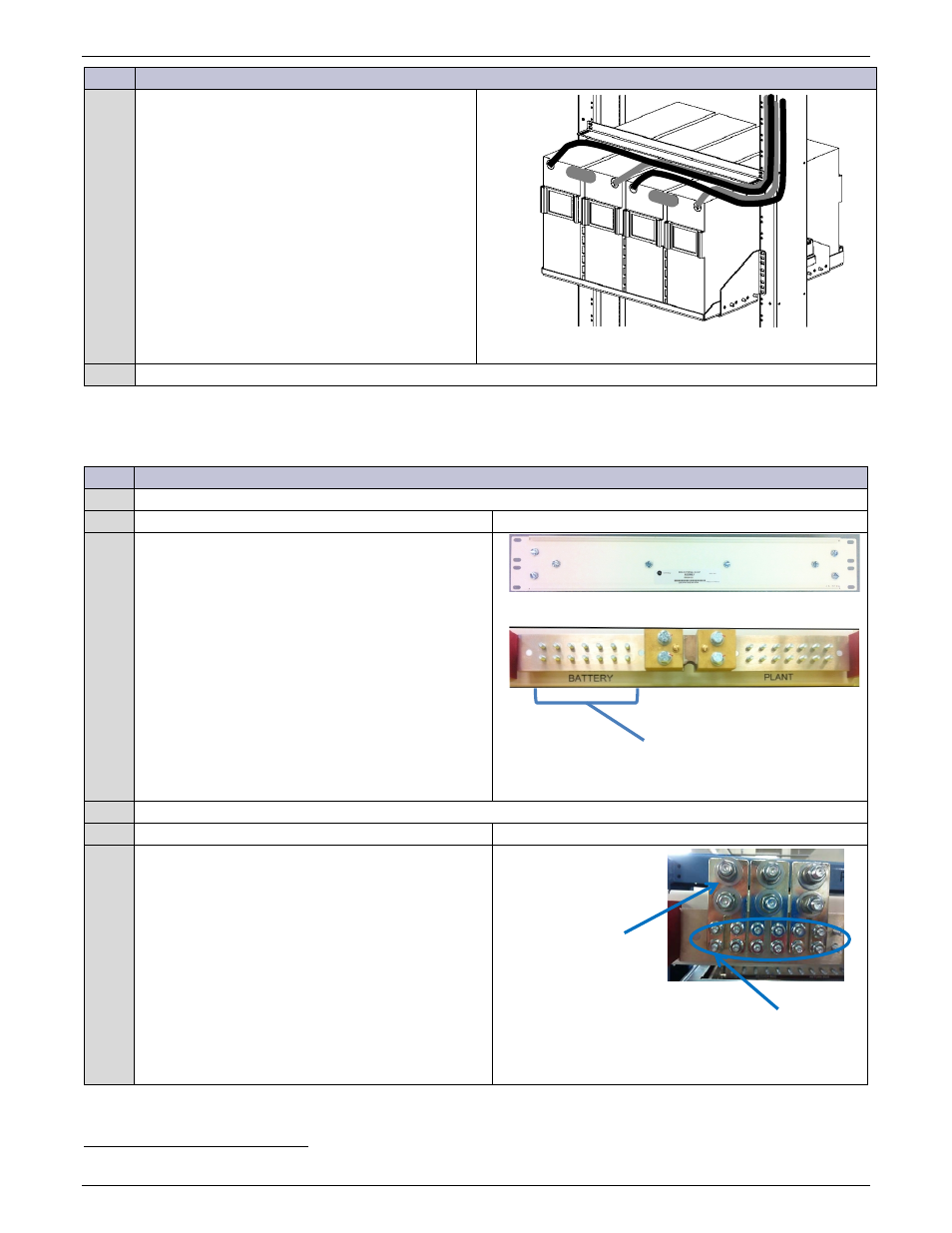
24V Battery Strings
Connect the factory-wired battery return cables
to the V- posts (left most posts) of both strings.
Torque to battery manufacturer’s specification.
Figure 48 Battery Return Cable Direct +24V
Battery installation is complete.
External Battery Connection
Step
Action
Is an external Battery Shunt panel installed
Yes – go to Step1.
No – go to Step4.
1
Battery Landings are 1/4-20 studs on 5/8” centers
spaced 3/4” apart (7 landings).
Lug adaptors use 2 landing positions and provide
3/8-16 studs on 1” centers (provided).
Figure 49 External Battery Shunt Panel
Are lug adapters required?
Yes – go to Step2.
No – go to Step3.
2
Install Lug Adapters
Remove 1/4-20 nuts (4) from landing.
Place lug adapter
Secure lug adapter with 1/4-20 nuts (4).
If required by local code or practice, treat with an
oxidation inhibitor such as NO-OX.
Torque to 65 in-lb - 7/16” socket.
Figure 50 External Battery Shunt Panel Lug Adapters
16
Eco systems less than 600A use an external battery panel.
External Battery Connections
¼-20 Studs
Lug Adapter