Connect battery probes, Verify battery bus voltage and polarity, Figure 51 external shunt panel battery connections – GE Industrial Solutions H5692448 Power Systems Infinity M1 (NE-M) User Manual
Page 34: Figure 52 battery bus connections
NE-M
Installation Guide
H5692448
CC848815325 r06 May 2013
34
Step
Action
3
Battery Cable Connections to External Shunt
Panel
(Battery only, not Return)
(see Step 4 for Battery Return Connections)
Secure Battery Cable lugs with hardware (per cable):
(2 sets) nut, lock washer, and flat washer.
If required by local code or practice, treat with an
oxidation inhibitor such as NO-OX.
Torque 1/4 -20 nuts to 65 in-lb - 7/16” socket.
Torque 3/8-16 nuts to 240 in-lb - 9/16” socket.
Figure 51 External Shunt Panel Battery Connections
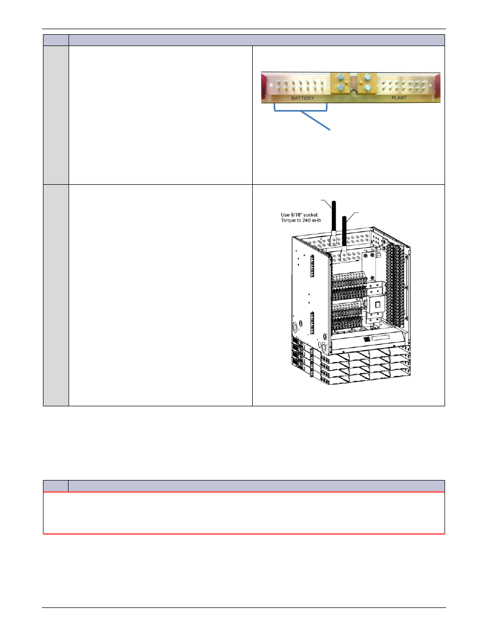
4
Battery Return Cable Connections (all)
and
Battery Cable Connections without External
Shunt Panel
See Step 3 for Battery Cable Connections to
External Battery Panel.
Secure Battery Cable lugs with hardware (per cable):
(2 sets) 3/8-16 nut, lock washer, and flat washer.
If required by local code or practice, treat with an
oxidation inhibitor such as NO-OX.
Torque to 240 in-lb - 9/16” socket.
Note: Battery Landings are 3/8” studs on 1”
centers spaced 1.25” apart (11 landings).
For lugs wider than 1.25”, use every other
connection (6 total).
Figure 52 Battery Bus Connections
Connect Battery Probes
Battery probes are optional controller peripherals. See the See the controller manual and instructions accompany the
options.
Verify Battery Bus Voltage and Polarity
Step
Action
CAUTION
:
Equipment Damage
Do not install rectifiers before battery bus voltage and polarity has been verified.
Rectifiers and system damage will result from incorrect battery bus polarity.
The damage may not be immediately evident.
External Battery Connections
Battery Return
All
Battery
(without External
Shunt Panel)