Figure 30 input jumper dividers, Figure 31 ac bridging jumper, Figure 32 input panel sections – GE Industrial Solutions H5692448 Power Systems Infinity M1 (NE-M) User Manual
Page 25
NE-M
Installation Guide
H5692448
CC848815325 r06 May 2013
25
Step
Action
2
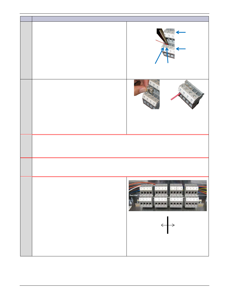
Snap loose L1 and L2 plastic dividers on Input terminal
blocks for each single fed rectifier pair.
Figure 28 shows rectifier AC dual feed jumper positions.
Figure 30 Input Jumper Dividers
3
Install AC bridging jumpers connecting each AC fed
rectifier pair L1 positions.
Install AC bridging jumpers to connect each AC fed
rectifier pair L2 positions.
Torque to 10 in-lb.
Figure 31 AC Bridging Jumper
4
CAUTION: Equipment Damage or Malfunction
NE-M Eco
systems must keep PV input feeds separate from AC input feeds.
The PV/AC partition separates PV inputs from AC inputs.
Connect PV input feeds only to the PV section of the Input Panel.
Connect AC input feeds only to the AC section of the Input Panel
CAUTION: Equipment Damage or Malfunction
NE-M Eco
systems PV input feeds must be connected as follows:
Positive PV to L1
Negative PV to L2.
5
Pull and terminate input feed wires to the terminal blocks
in the Input Panel.
• ac input feeds to the AC section of the Input
Panel
• PV input feeds to the PV section of the Input
Panel
Positive PV to L1
Negative PV to L2.
Torque to 10 in-lb.
Figure 27 shows rectifier and shelf numbering.
Figure 32 Input Panel Sections
L2
L1
R1
R1
Snap Loose
Divider
with Pliers
R13 and R14
L1 AC feed
R13 and R14
L1 Bridging Jumper
PV/AC Partition
Eco
only
PV Section
NE-M
Eco only
ac Section
NE-M
Eco only