Active line tracing, Measuring depth, Clipping – RIDGID NaviTrack II User Manual
Page 15
NaviTrack® II
14
Measuring Depth
The NaviTrack® II measures depth by comparing the strength
of the signal at the lower antenna to the upper antenna.
Depth is measured correctly when the mast is held vertical and
the bottom antenna is touching the ground directly above the
signal source.
1. To measure depth, place the locator on the ground,
directly above the sonde or the line.
2. Depth will be shown in the lower left-hand corner of
the NaviTrack® II’s display screen.
3. A depth reading can be forced by pressing the select
key during a locate.
Clipping
Occasionally the signal strength will be strong enough that the
receiver will be unable to process the whole signal, a condition
known as “clipping”. When this occurs a warning symbol
will appear on the screen. It means that the signal is particularly
strong. When locating a line, if clipping persists, remedy it by
reducing the strength of the current from the transmitter.
Clipping is unlikely to occur in Sonde locating, and would
indicate the receiver was very close to the sonde.
Active Line Tracing
In active line tracing, underground lines (lines that can “carry”
an electromagnetic signal (thus plastic pipes cannot be located
this way)) are energized with a line transmitter. This active
signal is then traced using the NaviTrack® II. A line transmitter is
different from a sonde in that it is used for tracing an energized
line, rather than acting as a target for a locate as a sonde is. Line
transmitters energize lines by direct connection with clips, by
directly inducing a signal using a clamp, or by inducing the
signal using inductive coils built in to the transmitter.
1. Energize the line according to the manufacturer’s
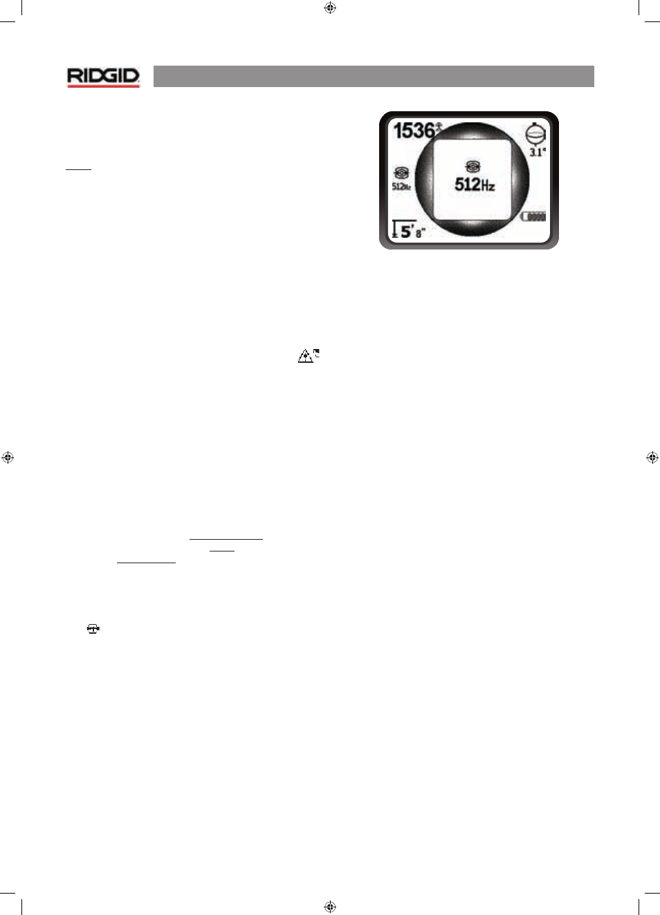
instructions. Select the transmitter frequency.
Set the frequency used on the NaviTrack® II to the same
frequency used on the transmitter. Be sure it has a line trace
icon
. Push the main menu button to return to the map
display.
Figure 23: Line Trace Frequency Chosen
With the Frequency Button
2. Observe the Proximity Signal to ensure the NaviTrack® II
is picking up the transmitted signal. The signal should
peak over the line and drop off on either side.
3. When tracing, the direction the pipe or cable is running
will be shown on the screen with 2 lines, one solid and
one dashed. The dashed line is the signal as seen by the
upper antenna node and the solid line is the signal as
seen by the lower one. The angle indicator will be near
zero if over the center of the field.
4. Use the Proximity Number, Signal Strength, and Signal
Trace Lines to guide the line trace. These three pieces
of information are generated from discrete signal
characteristics to help the locator discern the quality
of the locate. An undistorted signal emitted from a
line is strongest directly over that line. By maximizing
the Proximity Signal, and centering the Signal Trace
Lines on the screen the confidence in a “good” locate
is high. Confirm a locate by testing whether the depth
reading is stable and reasonable. One way to test for
the consistency of the depth reading by raising the
NaviTrack® II a known distance (say, 35 cm exactly) and
observing whether the depth indicator increases by
the same amount. Small variation is acceptable, but if
the depth does not change, or changes drastically, it is
an indication of a “distorted” field, or very low current
on the line. (As always, the only way to be completely
certain of the location of a utility is through visual
inspection by exposing the utility.)