5 scan if interrupts, Table 24−7.scan if interrupts – Texas Instruments MSP430x4xx User Manual
Page 487
Scan IF Operation
24-27
Scan IF
24.2.5 Scan IF Interrupts
The Scan IF has one interrupt vector for seven interrupt flags listed in
Table 24−7. Each interrupt flag has its own interrupt enable bit. When an
interrupt is enabled, and the GIE bit is set, the interrupt flag will generate an
interrupt. The interrupt flags are not automatically cleared. They must be
cleared with software.
Table 24−7.Scan IF Interrupts
Interrupt
Flag
Interrupt Condition
SIFIFG0
SIFIFG0 is set by one of the AFE SIFxOUT outputs selected with the
SIFIFGSETx bits.
SIFIFG1
SIFIFG1 is set by the rising edge of the SIFSTOP(tsm) signal.
SIFIFG2
SIFIFG2 is set at the start of a TSM sequence.
SIFIFG3
SIFIFG3 is set at different count intervals of the SIFCNT1 counter,
selected with the SIFIS1x bits
.
SIFIFG4
SIFIFG4 is set at different count intervals of the SIFCNT2 counter,
selected with the SIFIS2x bits.
SIFIFG5
SIFIFG5 is set when the PSM transitions to a state with Q6 set.
SIFIFG6
SIFIFG6 is set when the PSM transitions to a state with Q7 set.
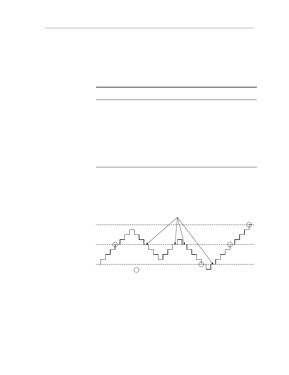
Interrupt flags SIFIFG3 and SIFIFG4 have hysteresis so that the interrupt flag
is set only once if the counter oscillates around the interrupt level as shown in
Figure 24−13.
Figure 24−13. Interrupt Hysteresis Shown For Modulo 4 Interrupt Generation
1
2
3
4
5
6
7
8
0
255
9
SIFCNT1
Interrupt Flag Not Set
Interrupt Flag Is Set