Dtm leds – Nortel Networks BCM50 User Manual
Page 67
Chapter 3 Viewing the BCM50 system LEDs
67
Installation and Maintenance Guide
The table
on page 67 describes the possible MBM LED states.
DTM LEDs
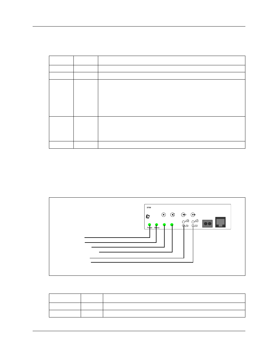
The DTM has additional LEDs that are not on most other MBMs. The figure
67 shows the location of the DTM LEDs.
Figure 31 DTM LEDs
The table
on page 67 describes the functions of the DTM LEDs.
Table 14 MBM LED descriptions
Power Status
Description
Off
Off
The MBM has no power, or a failure occurred on the MBM power converter.
On
Off
BCM50 to expansion unit failure or system initialization.
On
Blinking
Hardware is working, but an operational problem exists such as:
•
no link to the main unit is detected
•
frame alignment is lost on messages from the main unit
•
bandwidth not allocated
•
MBM is in maintenance state
•
MBM is in download state (GASM, GATM4/GATM8)
Blinking
Blinking
The MBM has power, but a hardware problem exists such as:
•
partial failure of power converter
•
thermal overload
•
fan failure
On
On
The MBM is ready to operate.
Table 15 DTM LED functions (Sheet 1 of 2)
LED Status
Descriptions
Power
–
See
“Media bay module LEDs (expansion units only)”
for details.
Status
–
See
“Media bay module LEDs (expansion units only)”
for details.
Power LED
Status LED
In service LED
Loopback test LED
Receive LEDs
Transmit LEDs