Bri wiring chart, Appendix b bri wiring chart, Appendix b – Nortel Networks BCM50 User Manual
Page 207
Appendix B BRI wiring chart
207
Installation and Maintenance Guide
Appendix B
BRI wiring chart
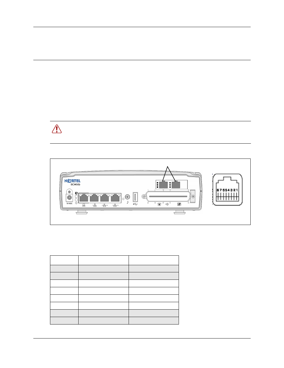
The digital BRI ISDN lines connects to the BCM50b, BCM50ba, and BCM50be main units
through the BRI ports (RJ-45) on the front of the main units. See the figure
BRI ports and pin out (BCM50b shown)
on page 207, the table
207, and the table
on page 208 apply to S-Loop and T-Loop connections.
S-Loop are used to connect S-Loop devices such as video phones, terminal adapters, and Grp 3
Fax machines. The T-Loops are used to connect to the CO/PSTN.
Figure 88 BRI ports and pin out (BCM50b shown)
The table
on page 207 and the table
on page 208 list the
wiring details for the RJ-45 ports.
Warning: For a U-loop connection, the BRI port must be connected only to an NT1
provided by the service provider. The NT1 must provide a Telecommunication Network
Voltage (TNV) to Safety Extra Low Voltage (SELV) barrier.
Table 35 BRI port wiring
Pin
Signal
Signal on system side
1
No connection
No connection
2
No connection
No connection
3
+ Receive (+Rx)
+Tx
4
+ Transmit (+Tx)
+Rx
5
- Transmit (-Tx)
-Rx
6
- Receive (-Rx)
-Tx
7
No connection
No connection
8
No connection
No connection
BRI port pin out
BRI ports