Power connector – Sierra Wireless 20070914 User Manual
Page 26
Specifications
Rev 3.0B Feb.08
13
I/O Port
Figure 2-2: PinPoint X I/O Port Diagram (not to scale)
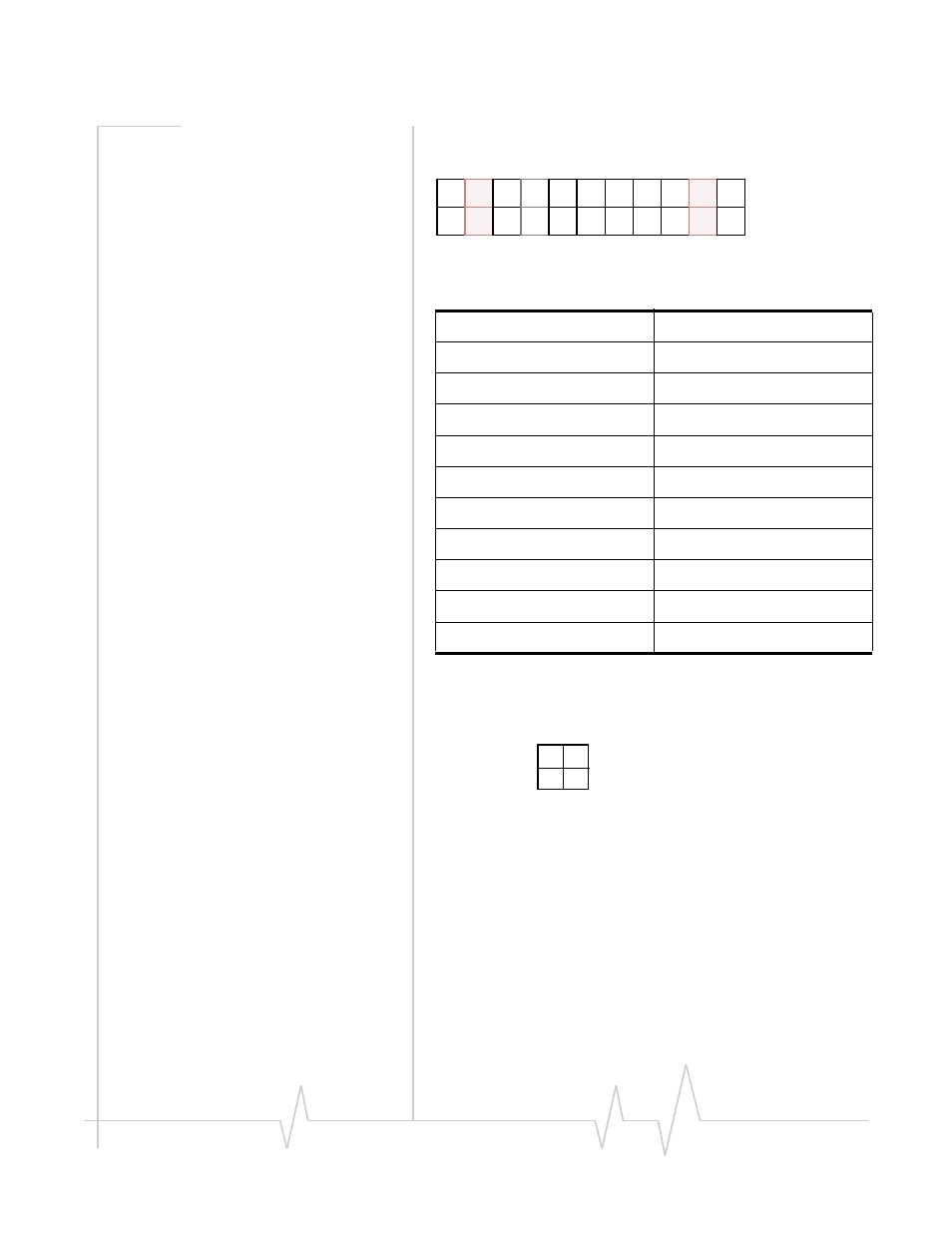
Power Connector
Figure 2-3: Power Connector (not to scale)
Table 2-1: PinPoint X I/O Port Pin-out
1.
Analog Input 4
12.
Analog Input 3
2.
Analog Ground
13.
Analog Ground
3.
Analog Input 2
14.
Analog Input 1
4.
No Connect
15.
No Connect
5.
Reserved for future use
16.
Reserved for future use
6.
Com2 (for use with #7)
17.
Com1 (for use with #18)
7.
Normal Open Relay
18.
Normal Open Relay
8.
None
19.
None
9.
Digital Input 4
20.
Digital Input 3
10.
Ground
21.
Ground
11.
Digital Input 2
22.
Digital Input 1
GND
GND
1
2
3
4
5
6
7
8
9
10
11
12
13
14
15
16
17
18
19
20
21
22
GND
GND
NC
NC
Rsv
Rsv
AIN3
AIN4
AIN1
AIN2
DIN1
DIN2
DIN3
DIN4
Relay 1
Relay 2
Com2
Com1
NO2
NO1
Ignition Sense (white)
Power (red)
Ground (black)
Not Used