4 system clock oscillator, 1 main system clock oscillator – IBM uPD78082 User Manual
Page 96
73
CHAPTER 5 CLOCK GENERATOR
5.4 System Clock Oscillator
5.4.1 Main system clock oscillator
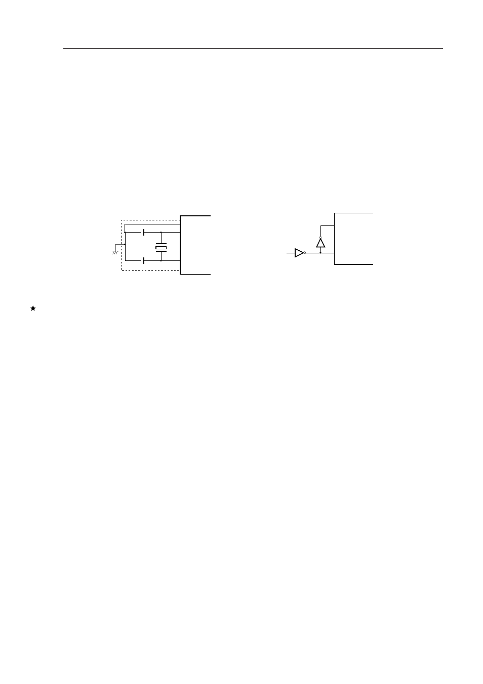
The main system clock oscillator oscillates with a crystal resonator or a ceramic resonator (standard: 5.0 MHz)
connected to the X1 and X2 pins.
External clocks can be input to the main system clock oscillator. In this case, input a clock signal to the X1 pin
and an antiphase clock signal to the X2 pin.
Figure 5-5 shows an external circuit of the main system clock oscillator.
Figure 5-5. External Circuit of Main System Clock Oscillator
(a) Crystal and ceramic oscillation
(b) External clock
Cautions 1. Do not execute the STOP instruction if an external clock is used. This is because the X2 pin
is connected to V
DD
via a pull-up register.
2. When using a main system clock oscillator, carry out wiring in the broken line area in Figure
5-5 to prevent any effects from wiring capacities.
●
Minimize the wiring length.
●
Do not allow wiring to intersect with other signal conductors. Do not allow wiring to come
near changing high current.
●
Set the potential of the grounding position of the oscillator capacitor to that of V
SS
. Do
not ground to any ground pattern where high current is present.
●
Do not fetch signals from the oscillator.
Figure 5-6 shows examples of oscillator having bad connection.
Crystal
or
Ceramic Resonator
IC
X1
X2
X1
PD74HCU04
µ
X2
External
Clock