IBM uPD78082 User Manual
Page 202
179
CHAPTER 12 INTERRUPT FUNCTION
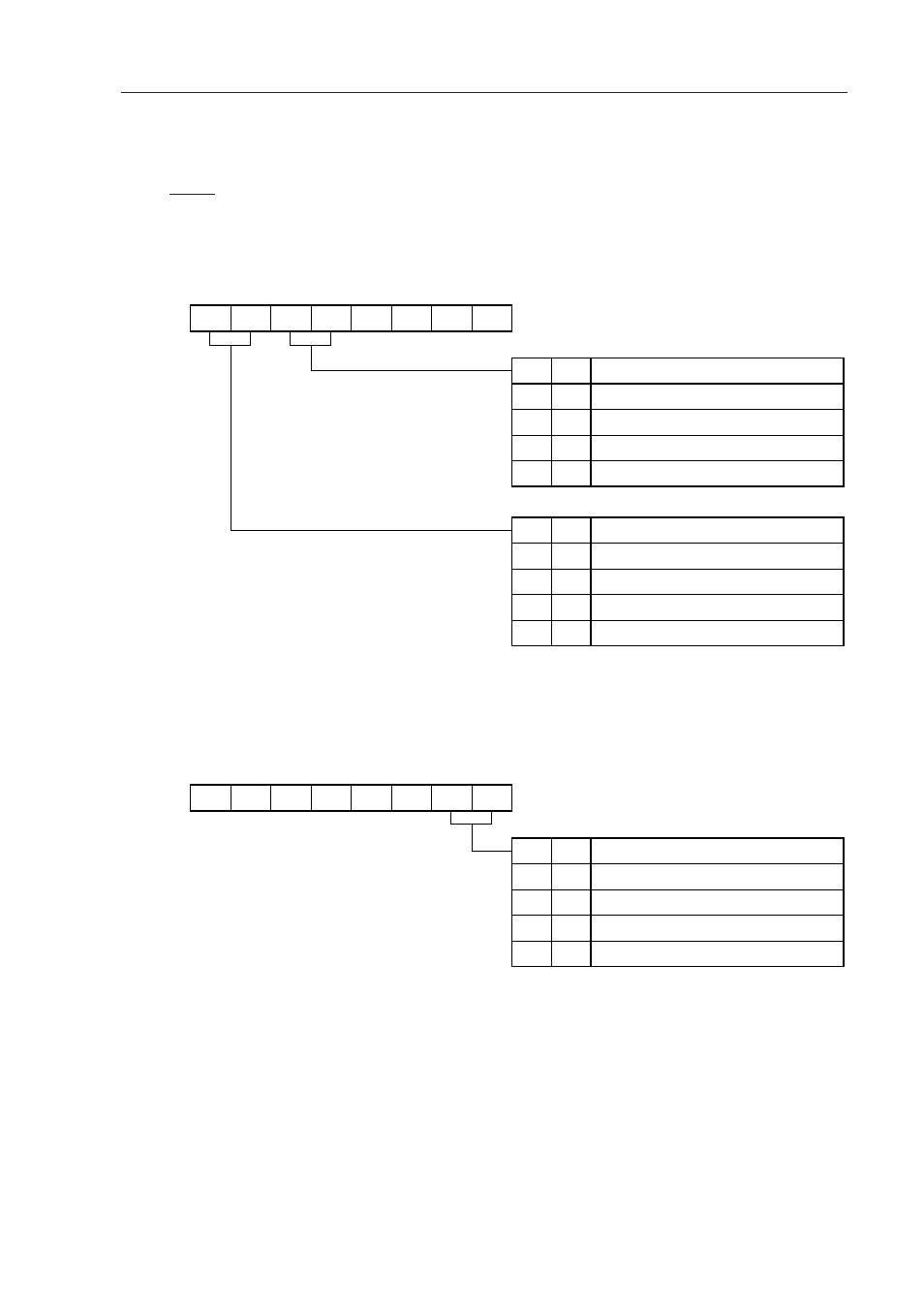
(4) External interrupt mode register (INTM0, INTM1)
These registers set the valid edge for INTP1 to INTP3.
INTM0 and INTM1 are set by 8-bit memory manipulation instructions.
RESET input sets these registers to 00H.
Figure 12-5. External Interrupt Mode Register 0 Format
Caution
Set 0 to the bits 0 to 3.
Figure 12-6. External Interrupt Mode Register 1 Format
Address
FFECH
00H
After
Reset
R/W
R/W
7
ES31
Symbol
INTM0
6
ES30
5
ES21
4
ES20
3
0
2
0
1
0
0
0
0
0
1
1
INTP1 Valid Edge Selection
Falling edge
Rising edge
Setting prohibited
Both falling and rising edges
ES21
0
1
0
1
ES20
0
0
1
1
INTP2 Valid Edge Selection
Falling edge
Rising edge
Setting prohibited
Both falling and rising edges
ES31
0
1
0
1
ES30
Caution
Set 0 to the bits 2 to 7.
Address
FFEDH
00H
After
Reset
R/W
R/W
0
0
1
1
INTP3 Valid Edge Selection
Falling edge
Rising edge
Setting prohibited
Both falling and rising edges
ES41
7
0
Symbol
INTM1
6
0
5
0
4
0
3
0
2
0
1
ES41
0
ES40
0
1
0
1
ES40