Chapter 2 pin function, 1 pin function list, 1 normal operating mode pins – IBM uPD78082 User Manual
Page 38: Chapter 2 pin function 2.1 pin function list
15
CHAPTER 2 PIN FUNCTION
CHAPTER 2 PIN FUNCTION
2.1 Pin Function List
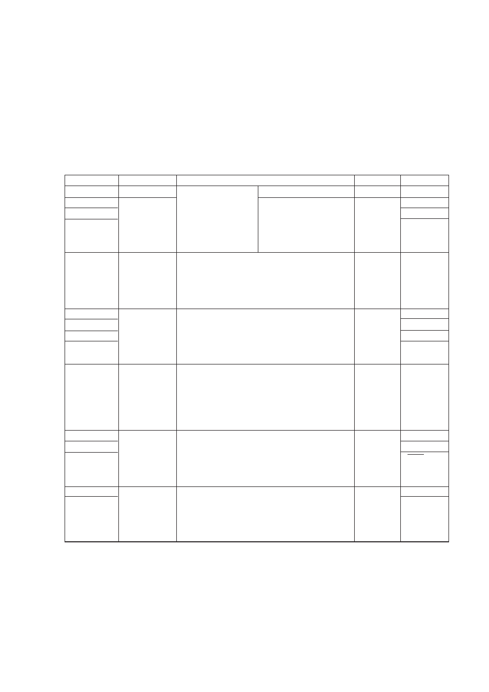
2.1.1 Normal operating mode pins
(1) Port pins
Note
When P10/ANI0-P17/ANI7 pins are used as the analog inputs for the A/D converter, set the port 1 to
the input mode. The on-chip pull-up resistor is automatically disabled.
Pin Name
Input/Output
Function
After Reset
Alternate Function
P00
Input
Port 0
Input only
Input
—
P01
Input/output
4-bit input/output port
Input/output is specifiable
Input
INTP1
P02
bit-wise. When used as the
INTP2
P03
input port, it is possible to
INTP3
connect a pull-up resistor by
software.
P10-P17
Input/output
Port 1
Input
ANI0-ANI7
8-bit input/output port
Input/output is specifiable bit-wise.
When used as the input port, it is possible to connect
a pull-up resistor by software.
Note
P30-P34
Input/output
Port 3
Input
—
P35
8-bit input/output port
PCL
P36
Input/output is specifiable bit-wise.
BUZ
P37
When used as the input port, it is possible to connect
—
a pull-up resistor by software.
P50-P57
Input/output
Port 5
Input
—
8-bit input/output port
A maximum of 7 out of 8 ports can drive LEDs directly.
Input/output is specifiable bit-wise.
When used as the input port, it is possible to connect
a pull-up resistor by software.
P70
Input/output
Port 7
Input
SI2/RxD
P71
3-bit input/output port
SO2/TxD
P72
Input/output is specifiable bit-wise.
SCK2/ASCK
When used as the input port, it is possible to connect
a pull-up resistor by software.
P100
Input/output
Port 10
Input
TI5/TO5
P101
2-bit input/output port
TI6/TO6
Input/output is specifiable bit-wise.
When used as the input port, it is possible to connect
a pull-up resistor by software.