IBM uPD78082 User Manual
Page 31
8
CHAPTER 1 OUTLINE
Note
Under development
Cautions 1. (L)
: Connect individually to V
SS
via a pull-down resistor.
2. V
SS
: Connect to the ground.
3. RESET : Set to the low level.
4. Open
: Do not connect anything.
A0 to A14
: Address Bus
RESET
: Reset
CE
: Chip Enable
V
DD
: Power Supply
D0 to D7
: Data Bus
V
PP
: Programming Power Supply
OE
: Output Enable
V
SS
: Ground
PGM
: Program
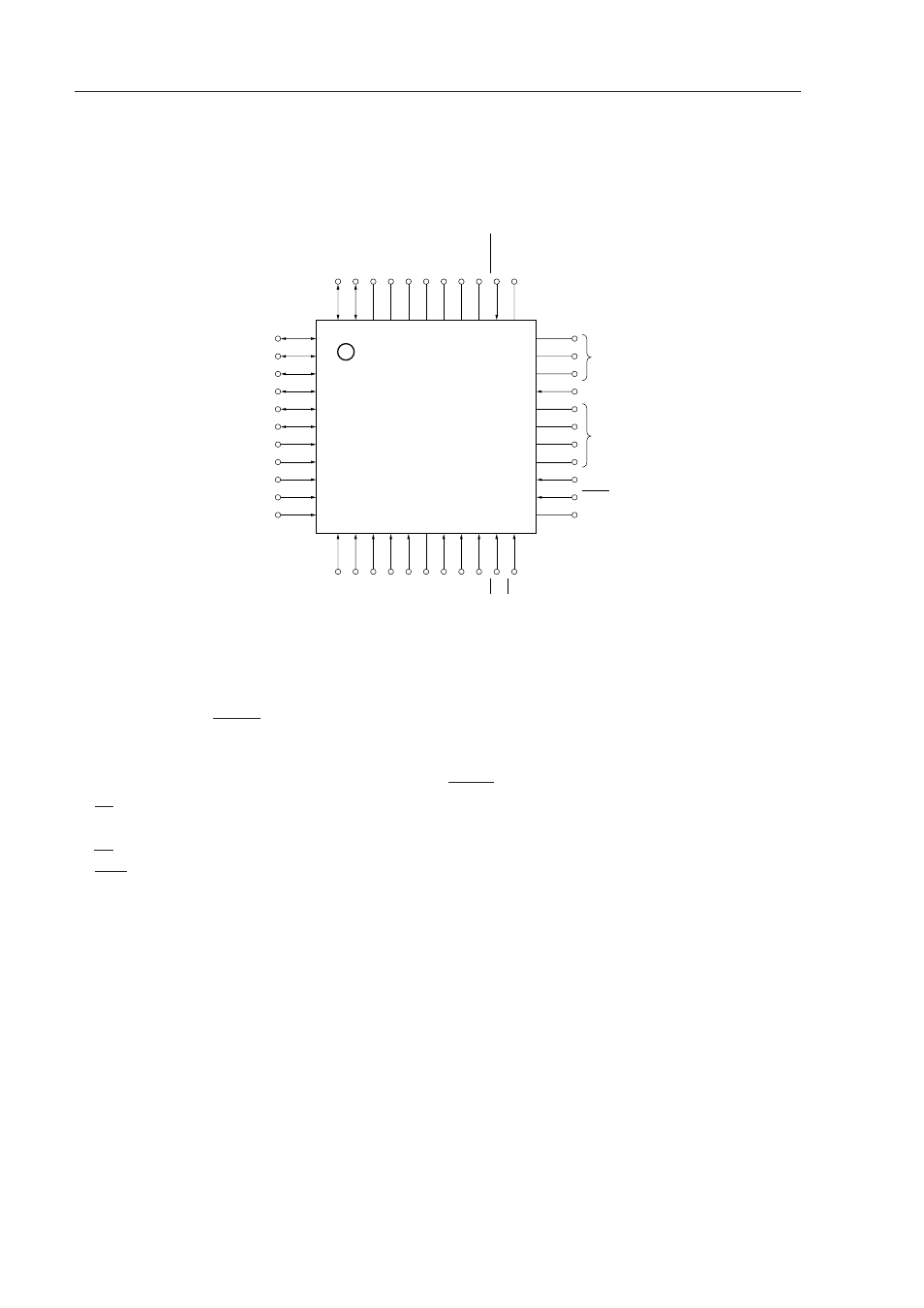
•
44-pin plastic QFP (10
×
10 mm)
µ
PD78P083GB-3B4, 78P083GB-3BS-MTX
µ
PD78P083GB(A)-3B4, 78P083GB(A)-3BS-MTX
Note
1
2
3
4
5
6
7
8
9
10
11
A9
A8
PGM
(L)
33
32
31
30
29
28
27
26
25
24
23
D2
D3
D4
D5
D6
D7
A14
A13
A12
A11
A10
D1
D0
V
SS
V
SS
V
DD
V
DD
(L)
Open
V
PP
RESET
(L)
A0
A1
A2
A3
A4
V
SS
A5
A6
A7
OE
CE
12 13 14 15 16 17 18 19 20 21 22
44 43 42 41 40 39 38 37 36 35 34
(L)
(L)