Power indicators (2412 and larger models only), Button icons, Power supply leds – Extron electronic Ultra Series User Manual
Page 54: Operation, cont’d
Operation, cont’d
CrossPoint / MAV Matrix Switchers • Operation
3-10
Power indicators (2412 and larger models only)
i
Primary and Redundant Power Supply LEDs —
Green —
Indicates that the associated power supply is operating within
normal tolerances.
Red —
Indicates that the associated power supply is operating outside the
normal tolerances or has failed.
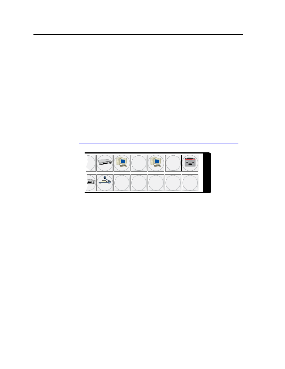
Button icons
The numbered translucent covers on the input and output pushbuttons can be
removed and replaced to insert labels behind the covers.
Input and output labels can be created easily with Extron’s Button-Label Generator
software, which ships with every Extron matrix switcher. Each input and output
can be labeled with names, alphanumeric characters, or even color bitmaps for
easy and intuitive input and output selection (figure 3-4). See chapter 5, “Matrix
Software”, for details on using the labeling software. See Appendix B, “Reference
Information”, for blank labels and a procedure for removing and replacing the
translucent covers.
DVD
VCR
Computer
Computer
Document
Camera
VTG 200
10
13
15
29
28
30 31 32
I
N
P
U
T
S
Figure 3-4 — Sample button icons