Algorithm basics, Algorithm basics -34 – Kurzweil Forte User Manual
Page 131
Program Edit Mode
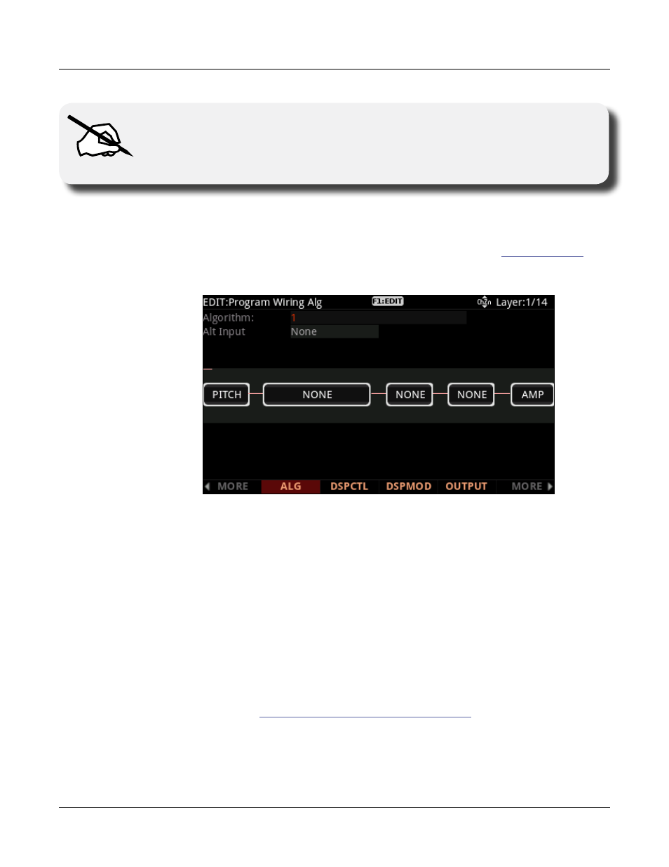
The Wiring Algorithm (ALG) Page
7-34
Note
: Changing a layer’s algorithm can affect the layer’s sound drastically. It’s a good
idea to bring down the volume of your Forte or your sound system before changing
algorithms.
Algorithm Basics
Each of the available algorithms represents a preset signal path. (See the
section below for details on making user algorithms with custom signal paths.) Take a look at
Algorithm 1 in the diagram below. It’s one of the simplest algorithms.
The DSP functions are represented by the rectangular blocks. The lines connecting the blocks
together indicate the flow of the digital signal from left to right; they represent the “wiring”
of the algorithm: the path that the signal follows through the algorithm. Selecting different
algorithms can be compared to connecting different DSP functions with different wiring
diagrams.
Think of the left side of each block as its input, and the right side as its output. Depending
on the algorithm, the signal may split into two wires, enabling part of the signal to bypass
certain portions of the algorithm. Split wires may rejoin within the algorithm, or they may
pass all the way through as split signals. If the last block has two wires at its output, we call it
a double-output algorithm. If it has one wire, it’s a single-output algorithm, even if there are
two wires in earlier portions of the algorithm.
Each block of the algorithm represents a certain function in the signal path. In every non-
cascaded algorithm (see
Alt Input for Algorithms (Cascade Mode)
below), the signal flows
first through a one-stage DSP function that controls the pitch of the samples in the keymap
(this function is represented as a block labeled PITCH). In fact, the first DSP function in